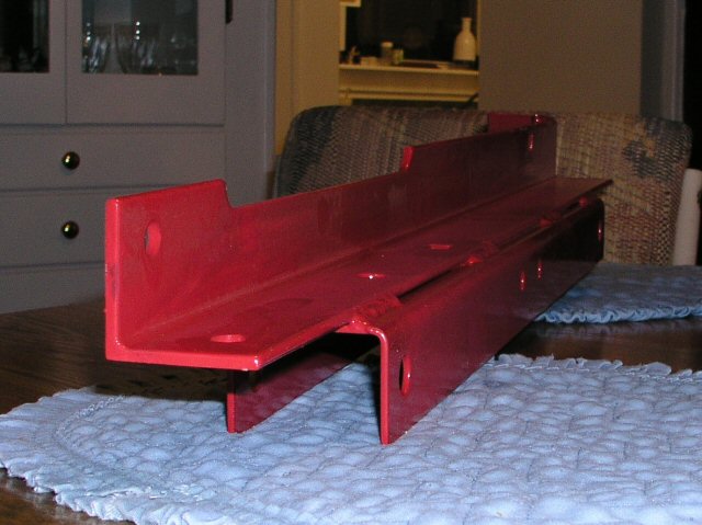
Page 5 of 17

Channel

PostPosted: Fri Feb 24, 2006 3:36 pm
by Guy
Dear Andrew,

What about using Channel with the opening outside for the A-frame tongue? Then Mike can extend the A-frame to his torsion axel brackets with very little weight gain and create a full triangle.

PostPosted: Fri Feb 24, 2006 5:11 pm
by Chuck Craven
C channel has 1/3 the strength of square tubing by weight.

Chuck

PostPosted: Fri Feb 24, 2006 5:18 pm
by Jiminsav
the rubber dosn't go through the length of the torsion axle..maybe a foot in on each side, all the solid axle does is position the wheels perpendicular to each other, if you line it up right..i used half shaft torsion axles on my trailer without any problem except i didn't get the wheels perpendicular to the center line and it had a little shimmy..i shimmed it up and Viola'..works like a champ
a pic of the axles temp bolted to frame Image

rubber suspension

PostPosted: Fri Feb 24, 2006 7:46 pm
by Mitheral
angib wrote:
Mitheral wrote:No where near the centre. To get an idea look how short the non axle units are.

I think the suspension pivots and rubber rods may be longer in full axles, but this photo of a Henschen axle certainly suggest they don't get anywhere near the middle:


I rented shop space from a couple guys making these kinds of axles for a couple months. They were using round rubber rather than the triangular pieces shown. For custom axles they could tune the axle to match an exact weight rating by adjusting the length of the insert. IE: say the insert supported 200lbs per inch. They could make a 2000 lb axle (10 inches long total 5 inches per side) or a 3250 lb axle (16.25 inches total) or a 5600 axle (28 inches total). What ever the customer wanted. I don't think even 7000 lb inserts were more than 18 inches long. Larger axles used larger diameter rubber. If they made the insert too long the steel centre section would start twisting.

PostPosted: Fri Feb 24, 2006 7:53 pm
by mikeschn
Okay I'm back at the drawing board...

I'm still waiting to hear from our resident engineer, but I picked up an axle and wheels today for the Ultralight. Unfortunately it came with hundreds of pounds of excess metal that I had to lug out of the car and throw into the garage.

But I found this piece, and I'm thinking if I mount this underneath the wall and the floor, and bolt it in from both directions, that I'll get the benefit of the strength of the wall. Did I say that right Andrew?

Anyways, here's the angle in question...
Image

I might be able to use the 50* tongue too!

Mike...

Did that come with it

PostPosted: Fri Feb 24, 2006 7:56 pm
by Guy
Dear Mike,

Did that piece come with the axle?

Re: Did that come with it

PostPosted: Fri Feb 24, 2006 8:08 pm
by mikeschn
Guy wrote:Dear Mike,

Did that piece come with the axle?


Yep, along with all this stuff...

Image

If you don't recognize that yet, it's the 1175# HF trailer. It was on sale, plus the 20% discount... (you guys are good!)

I picked this up for a fraction of the cost of a flexiride axle, custom wheels, custom metal for the tongue and the axle mounting...

Mike...

PostPosted: Fri Feb 24, 2006 8:19 pm
by Nitetimes
I think if a guy were to notch the side of the floor so that was inset flush (so the wall could come down and cover it) and bolted it on with the tongue welded to the front of that in an A-frame configuration you would wind up with what you are looking for. Make sense? 8) 8) :thumbsup:

PostPosted: Fri Feb 24, 2006 8:40 pm
by bg
Mike,

Can you post a picture without the gradient in the background?

PostPosted: Fri Feb 24, 2006 8:42 pm
by mikeschn
Sure BG, which picture are you looking for...?

Mike...

PostPosted: Fri Feb 24, 2006 8:43 pm
by bg
the profile outline

PostPosted: Fri Feb 24, 2006 8:56 pm
by mikeschn
Okay BG,

Here's where I am at right now...

Image

I'll be cleaning this picture up in the morning... I'll also be tweaking the design to use the HF 1175# axle. Did you catch my xy points in another message in this thread. Those numbers are still good. They won't change...

Mike...

PostPosted: Fri Feb 24, 2006 8:57 pm
by Chuck Craven
Ok Mike! You just made a major change! The stress thing is all different on this. So take your 4” grinder and get rid of the paint on the inside edges of the angle iron. Now 2” square tubing from the back of the angle iron to the front weld it, inside the angle iron spring hangers. At the front of the 2” and angle iron point you need to cut a v notch in the sqr tubing not all the way through. Its an inside v notch. Bend the tubing in, to form the tongue, same on the other side. Weld the closed v notch closed. With the flex ride axel all that would be needed is to bolt/weld the axel to the 2” sqr tubing. One may have to weld another piece of 2” parallel with the mounting plat to make it a little stronger. But with springs you need to take a 2” sqr tube from the center of 2” tubing, where the spring hangers are welded. And weld it parallel with the axel, from one side to the other side. Now you have a triangle, weld some small angle iron pieces to the tongue to bolt the floor plywood too. Don’t bolt through the 2” sqr tubing that may give you a weak spot for stress cracking. On top of the plywood floor use angle iron or angle aluminum like 1” X 1” all around the plywood edges to mount the walls to the floor. This will be your trailer frame. It just will be on the inside of the body. Tar the bottom of the plywood floor like normal before assembling. It should be quite light and strong! :twisted:
Chuck

PostPosted: Fri Feb 24, 2006 8:59 pm
by bg
Mike,

Thanks.

I did catch the XY points. I've got some experimenting to do.

PostPosted: Fri Feb 24, 2006 9:01 pm
by mikeschn
Here are the points for the top of the door...

Top of door
x, y

53, 44.45
57, 44.78
60, 44.93
63, 45
66, 44.94
69, 44.64
72, 44.06
75, 43.2
78, 42
81, 40.43

Mike...