Teardrops n Tiny Travel Trailersor t n ttt for short (tnttt.com) |
Atma Travelear, with Aluminum Frame
50 posts
• Page 1 of 4 • 1, 2, 3, 4
Atma Travelear, with Aluminum Frame
![]() by Debraizhot » Fri Nov 14, 2014 5:41 pm
by Debraizhot » Fri Nov 14, 2014 5:41 pm
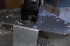
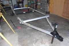
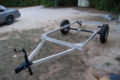
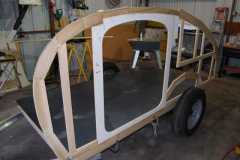
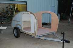
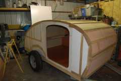
My wife and I fell in love with the elegance of design represented by Mr. McCamant's Travelear. So we are building one for us that we intend to pull behind our Prius. To do this we are working to get the total weight in below ~750#. We are using an aluminum frame that we made from scratch. To keep the weight low we opted not to weld but use structural adhesive and rivets. Attached are some pics of the progress.
-

Debraizhot - Teardrop Builder
- Posts: 33
- Images: 129
- Joined: Sun Aug 24, 2014 8:08 am
- Location: Paradise, Texas
Re: Atma Travelear, with Aluminum Frame
![]() by DrCrash » Fri Nov 14, 2014 8:12 pm
by DrCrash » Fri Nov 14, 2014 8:12 pm
I like it.
I did not stay at a Holiday inn last night nor am I an engineer.
I am questioning the tail end of the a frame under the perimeter of the frame..
Others will chime in but that makes me wonder..
I did not stay at a Holiday inn last night nor am I an engineer.
I am questioning the tail end of the a frame under the perimeter of the frame..
Others will chime in but that makes me wonder..
-

DrCrash - The 300 Club
- Posts: 489
- Images: 51
- Joined: Wed Feb 27, 2008 12:36 pm
- Location: N.W. Corner Ohio