Before I start, I really need to give a shout out to all the fine folks who helped me along the way...and by "helped me" I mean they answered a billion questions, lol. THANK YOU Andrew, SlowCowboy, Bob Henry, Rob48, WoodButcher, WarPony, and the countless others on here who exhibit true brilliance and skill for what they do.
Before jumping into the rebuild, here are some pix of the original build from three years ago. Two things really stuck out that made me want to remodel it - the wheels are WAY too far forward and there's no bathroom. As far as the wheels, I didn't' want to mess with moving the axle when I originally built the widget, so I ended up with wheels almost exactly down the center-line of the camper. This led to really bad handling and I ended up having to add a stabilizer. Luckily I had an A-frame tongue on the original camper so this was an easy task. My wheels were 8 inch wheels which looked retardedly small (I won't deny...it really looks out of proportion). Anyway, here are the pix
Here's the frame. It used to be an 85' Sunlite pop up camper. Took it down to the frame.
The walls are actually almost an inch thick - 3/4" maple veneered on the exterior side with 1/4" Cherry. This let me stagger the joints which led to incredible strength. The individual ply pieces are biscuit-joined and the overlapping Cherry plywood really holds it together. The spars are regular old 1x2 pine. I used some really bendy 1/4" "blondewood" ply from Home Depot that really made for a nice exterior roof. Used the same on the inside. In between the two layers I used some rigid 3/4" insulation and I ran all the wiring for the lights and the ceiling fan.
Don't be shy - you can say it....the wheels are WAY too small and need to moved back. So, that being the main driver for my remodel, I decided this spring to do a few things.
1. Replace the axle with a Flexiride, move it back about 8 inches to be in line with Andrew's original design, and upgrade to the plan specific 13 inch wheels.
2. Add a potty - I hate having to get up in the middle of the night and freeze my arse off as I go to the bathroom
3. Finally finish the exterior trim
Here's what I've got so far as far as the remodel goes. I've added in a port-hole window to the door, ordered the axle, and have modified the main rails slightly to accommodate it. I know the biggest thing that's going to pop up is - what am I going to do with the wheel cut outs on the side walls? Well, I LOVE LOVE LOVE the look of partially hidden wheels (like in the cabin car), so I've come up with a clever solution to doing that. More on that in later build pics. As for the potty, I've built in a 24" x 30" room to house the potty which is right next to one of the bunks (which is currently set up as a crib for our newborn). Our full-size bed will run the width of the camper (74") to the left of the camper entrance, and the second bunk will run perpendicular to that just over our feet. That bunk will only be about 5'8" long, but we figure it'll take our kids a while to get to that height so we should be good to go for a while. We had an AC in the old unit on a sliding shelf that was pushed out via a lockable door, but since I added the potty room I'll have to come up with a new place for that. I may do a tongue box in the same style as the camper (cherry sides and aspen trim) and then plumb in the intake and exhaust through the front roof. Here are the pictures that I have so far. We have a camping trip in October, so I'll be finishing this up between now and then and will be posting lots of pictures.
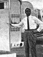
You can see the small exit door near the bottom-left of the picture. That's where the A/C used to slide out through in the original design.
This is an image from the passenger side looking into the camper. To the right is the crib (one day to be a regular bunk) and to the left running in the same plane as your line of sight is our bed.
Hope you guys enjoy the pix. There will be more in the following weeks. This week I'm working on installing the axle and seeing how it looks with the new wheels.
Cheers!

 I actually haven't even done them yet, but here's the general plan. I'm going to have to make the wheel opening larger now since I'm going from 8 inch to 13 inch wheels. To cover the opening I'm going to make a hinged cover that, on the outside, will look as if the side panel had never been cut. Basically like a hinged door that I can flip up when I need to change the tire. I'll see if I can make a sketch tomorrow and post a pix