WFCO converter

Anything electric, AC or DC

WFCO converter

Postby Hudsonite » Tue Jul 10, 2007 12:04 pm

I purchased a WFCO 25 amp converter on the advice of someone here, and now I realize I'm in way over my head. :cry: I have it mounted inside the camper, but am not sure what I need to do in terms of preparing to hook it up to the campground power source. If you can help, boy, I'd sure appreciate it. I'm almost to the point now that we'll be able to camp. Thanks in advance!
Hudsonite
Teardrop Builder
 
Posts: 44
Joined: Thu Aug 31, 2006 6:21 am
Location: Hudson, Ohio

Postby Keith B » Wed Jul 11, 2007 4:07 pm

This is what I did...does it help you out any?
Image

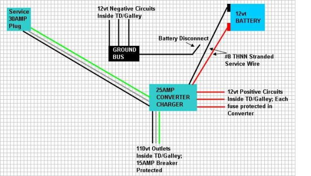
Now, what I did for a plug on the TD is cut the MALE end of the extension cord. This end is connected to converter and supplies the power to the outlets, charger, etc....so, all I need is an extention cord to go from the campground power to the TD male plug (which I have placed in my tongue box... please look at my album, it might give you a better idea of what I did, if not, please feel free to ask more questions.
************
Keith
"Work and work and do your best! Paint and putty will do the rest!"
User avatar
Keith B
Silver Donating Member
 
Posts: 550
Images: 148
Joined: Mon Jan 29, 2007 3:54 pm
Location: Wichita, KS

Postby Hudsonite » Thu Jul 12, 2007 5:06 am

Keith, Thanks much! It is extremely helpful. And your camper is top notch workmanship! Great job. I'm an admirer.

I do have one simple question... a newbie question, I'm sure... did you attach a ground from the male plug to the metal frame? I purchased a power inlet that I'm going to attach to the side of the camper, and it's got the little green screw to which I think I'm supposed to attach a ground wire. But the camper is wood, so I assume I have to go through the floor and attach it to the frame. What do you think?

Thanks again for the help, and all the great pictures in your album. I enjoyed going through them and seeing your TD progress.
Hudsonite
Teardrop Builder
 
Posts: 44
Joined: Thu Aug 31, 2006 6:21 am
Location: Hudson, Ohio
Top

Postby Keith B » Thu Jul 12, 2007 10:25 am

There's mixed concerns on this issue so I'm not going to say which is right or which is wrong...BUT... I did not attach a ground to my frame :D and I'm still alive....but I do have ground running to all the outlets - the ground will be acquired from the shore power you plug into. Good luck on your wire job, feel free to ask anyone for help. Look foward to seeing the finished project.
************
Keith
"Work and work and do your best! Paint and putty will do the rest!"
User avatar
Keith B
Silver Donating Member
 
Posts: 550
Images: 148
Joined: Mon Jan 29, 2007 3:54 pm
Location: Wichita, KS
Top

Postby Hudsonite » Fri Jul 13, 2007 8:35 pm

Keith,
I've been staring at the picture of your mounted converter, and I guess I'm still not getting it. As I look at mine, there is one main, thick black wire coming out the back that seems to be where the power would go into the converter. On the other side there are several wires of different colors that go to specific things (12 volt). I also have a couple of breakers that I can use for 120. My question is this: the power inlet that I bought has three screws on the back - positive, negative, ground (I think). How did you connect that big, black wire coming out the back of your converter to the "male plug" you use (my power inlet)?
Hudsonite
Teardrop Builder
 
Posts: 44
Joined: Thu Aug 31, 2006 6:21 am
Location: Hudson, Ohio
Top

Postby madjack » Fri Jul 13, 2007 8:56 pm

Hudsonite...a suggestion...goto the top of this page and click the search button and enter "WFCO" in the search window and hit "enter"...look at the threads, especially those originated by "kayakrguy" for all the info you can stand on this subject.......
madjack 8)
...I have come to believe that, conflict resolution, through violence, is never acceptable.....................mj
User avatar
madjack
Site Admin
 
Posts: 15128
Images: 177
Joined: Thu Dec 02, 2004 5:27 pm
Location: Central Louisiana
Top

Postby Hudsonite » Mon Jul 16, 2007 4:04 am

Thanks, Madjack. I've been working my way through the threads, and its been helpful. But my thick head just can't get over the hump. :thinking: I saw some nice photos of installations, but none of them really had a dead-on shot of the back of the WFCO so I could see it wired. I'll keep looking. :Oh Brother:
Hudsonite
Teardrop Builder
 
Posts: 44
Joined: Thu Aug 31, 2006 6:21 am
Location: Hudson, Ohio
Top

Postby Sonetpro » Mon Jul 16, 2007 5:34 am

I have the same converter. This is how mine is wired.

Image
}><)))'> ~--------------·´¯) SteveT
You don't know what the limit's are until you take it there.ImageImageImage
User avatar
Sonetpro
Site Admin
 
Posts: 2038
Images: 107
Joined: Sun Oct 30, 2005 8:11 am
Location: Plantersville, TX
Top

Postby Nobody » Mon Jul 16, 2007 12:19 pm

Hudsonite, you have a PM
Harvey -

- - - - - - - - - - - - - - - -

Doing the right thing ain't always easy but, . . . it's always right!
User avatar
Nobody
1000 Club
1000 Club
 
Posts: 1196
Images: 342
Joined: Wed Jan 25, 2006 1:09 pm
Location: Benton, Arkansas
Top

Postby Hudsonite » Tue Jul 17, 2007 5:55 am

Thanks all! It's beginning to sink in (about time!). Thanks Harvey for your explanation. Steve, what did you use to connect the shore power to the breaker? The WFCO comes with a thick black wire out the back. On your schematic, you have green/black/white "Shore Power Cable" coming in. Did you utilize the thick black wire already on the WFCO unit - connect it to another black - and then hook up green/white wires? And I assume the dotted white wire is the one pre-wired in the WFCO. The rest of the diagram is now clear to me.
Hudsonite
Teardrop Builder
 
Posts: 44
Joined: Thu Aug 31, 2006 6:21 am
Location: Hudson, Ohio
Top

Postby Nobody » Tue Jul 17, 2007 7:56 am

Scott, you mention the 'thick black cable' coming out the back of your converter. If you've determined absolutely, for sure that it is the 'shore power' wire, & if it is 'hard wired' i.e. soldered or machine 'crimped' to a lug or board, you can just connect the black (or red) wire from your shore power connector to it then wire the white (neutral) & green (ground) to the appropriate lugs as normal. I'd use an appropriate sized wire nut to connect the two, tho soldering is probably better but, if it's a # 10 or larger wire, it takes good sized soldering iron or small torch to do a proper solder job ;) . If you use a wire nut, leave enough length so the connection can be folded back on itself & taped securely. That should keep it from vibrating loose while being towed. At least that method has worked for me through many thousand miles of travel with various campers/trailers, etc, that I've had to re-wire or modify existing circuits :thumbsup:
Harvey -

- - - - - - - - - - - - - - - -

Doing the right thing ain't always easy but, . . . it's always right!
User avatar
Nobody
1000 Club
1000 Club
 
Posts: 1196
Images: 342
Joined: Wed Jan 25, 2006 1:09 pm
Location: Benton, Arkansas
Top

Postby Hudsonite » Tue Jul 17, 2007 7:09 pm

Thanks again, Harvey! I think you're right. I'll try some configuring and see what I can accomplish. Your explanation and Steve's schematic have helped. Perhaps once I've tried to make some progress I'll have more intelligent questions. I'll let you know.
Hudsonite
Teardrop Builder
 
Posts: 44
Joined: Thu Aug 31, 2006 6:21 am
Location: Hudson, Ohio
Top

Postby Hudsonite » Sun Jul 29, 2007 5:11 am

Steve, I have one question on your schematic. If I do not have a battery (at least for now), then how are the loads off the converter wired? I understand the blue/yellow/green/red wires go from the converter to the loads, but then what returns from the loads? Is it a ground wire from each load to the frame? It is probably obvious, but its the last piece of the puzzle for me. Thanks for your help.
Hudsonite
Teardrop Builder
 
Posts: 44
Joined: Thu Aug 31, 2006 6:21 am
Location: Hudson, Ohio
Top

Thanks!

Postby GeoDrop » Mon Nov 01, 2010 8:06 pm

I know this thread dates back nearly 4 years but thanks to Steve for posting this schematic! I was wondering what do do with that branch circuit wire!
Matthew (& Sandi)
The GeoDrop
User avatar
GeoDrop
Donating Member
 
Posts: 243
Images: 2
Joined: Mon Sep 07, 2009 9:45 pm
Location: Northeast Kansas
Top

Postby George Taylor » Mon Nov 01, 2010 9:30 pm

This info is for everyone. I am an electrician and there is a section in the NEC (National Electric Code) that deals with campers. All metal frames need to be connected (bonded)to the negative side of your electric service. This is a safety concern. The reason for this is to make the trailer frame the same potential as the negative side. if for some reason you were to lose the negative side connection (loos wire nut or stakon) and you were to accidentaly touch the frame and it was incontact with the ground you could become the path for the power to flow.
I know that this might sound far fetched, but it has happend in the past. take it from someone that has been the path for his share of 120 vols, it HURTS!
All you need to do is rune a #10 (#8 is better) copper wire to a ground lug screwed to the frame of the trailer. All of it can be bought at HD or Lowes.
George Taylor
Teardrop Master
 
Posts: 214
Images: 12
Joined: Sat Mar 13, 2010 9:18 pm
Location: New Boston, NH
Top

Next

Return to Electrical Secrets

Who is online

Users browsing this forum: No registered users and 2 guests