|
|
|
Close Help | ||||||||||||||
|
|
|
Close Help | ||||||||||||||
|
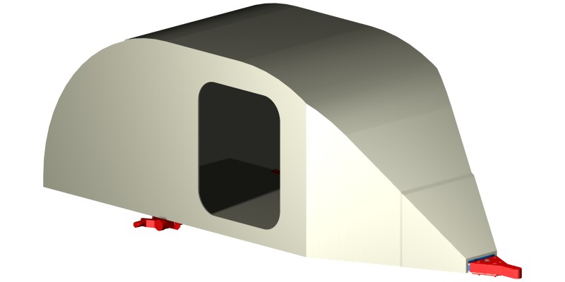
THE ALLWOOD
Introduction
This isn’t a design, as much as the starting point for a discussion. It is certainly not meant to something that a first-time teardrop builder could use.
The basic idea is to look at what sort of design is suitable to be built entirely in wood – or at least entirely in wood and epoxy, as wood and fasteners would certainly not be enough.
It is not a simple or cheap alternative to buying a metal frame to build a teardrop on – indeed, it will be more difficult and more expensive to build this way.
A significant skill set will also be required, starting with familiarity with epoxy-wood construction. It is unlikely that anyone who hasn’t built a boat (or an airplane) should start on an Allwood. The structure will be subject to cyclic fatigue loading, so cabinetmaking or housebuilding construction practice may not be suitable.
So why do it? Like mountain climbing, because it is there.
A very similar overall design could be used to build an all-composite teardrop with no metal frame.
The first and most obvious difference from a conventional teardrop is that there is no ‘frame’, as building wood imitation of a metal frame won’t work. Instead a monocoque or unibody overall design is used where the strength comes for the stressed skin construction.
This means that: (a) the joints between the skin panels matter a lot for the overall strength, and (b) the quality of the skin plywood also matters a lot.
For these reasons, it would be sensible to only build this design in marine plywood, which has a minimum standard for the quality of the invisible interior plies that no other plywood has. It’s no use using a plywood that may have interior voids just where maximum strength is required. Marine ply may be expensive and hard to obtain but this isn’t a cheap or easy design to build!
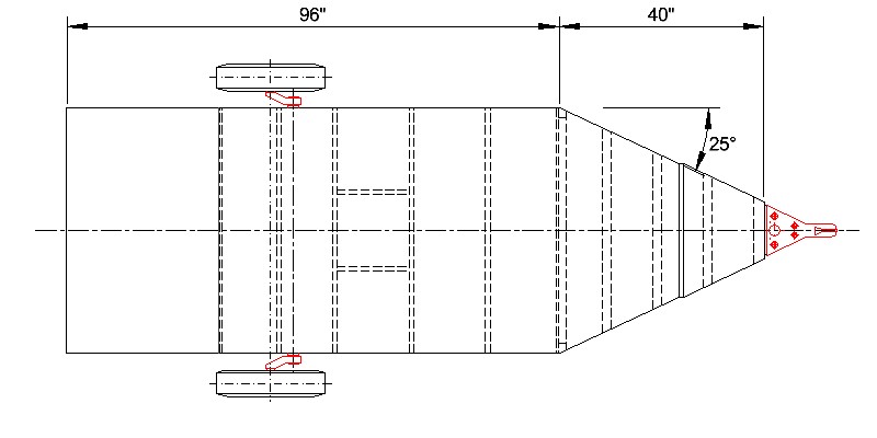
So the body of the teardrop is extended forwards and tapers in until the coupler is reached. To make the build a bit easier, the side walls taper in at 25 degrees to match the standard 50 degree coupler angle.
An overall bracing of the structure is provided by a bulkhead between the cabin and the tapering tongue. This bulkhead can have an opening in it to access the substantial space in the tongue, providing the remaining bulkhead is no narrower than 6” on any side. No other openings (well, no openings larger than say ½” diameter) are allowed anywhere in the tongue box, however convenient it looks as a tongue storage box.
Running Gear
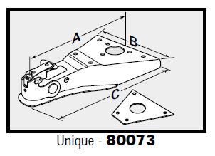
Atwood kindly make a bolt-on A-frame coupler (80073) that could have been designed for this job – it even comes with a reinforcing plate that fits under the tongue. It’s probably meant for boat trailers and has a galvanised finish, but suits this use fine. It’s a Class III coupler, good for trailer GVWRs up to 5000 lb, so it’s serious overkill for this application, but at least that means it has a good contact/bolting area to lower the contact stress on the wood.
A full torsion axle is shown as this puts the least stress on the trailer structure. For the expected weight of the trailer (500 lb, maybe?), torsion half axles would be a better choice, to get the suspension rating near the expected weight, but using those without a bulkhead above them to maintain geometry would require an over-built floor structure.
A bolting plate (10” x 2” x ¼”) is fitted either side above the floor over the axle mounts.
It is essential that the coupler and axle cannot start moving or fretting, so the assembly procedure would have to be: - axle and coupler dry-fitted with a loose fit; - all bearing surfaces and the inside of all bolt holes soaked in epoxy; - axle, coupler and reinforcing plates fitted with a polyurethane adhesive sealant (eg, Sikaflex) completely covering all bearing surfaces.
The adhesive sealant would make replacement of the coupler or axle possible, though not actually easy, and yet ensure that no fretting movement can occur between these parts and the woodwork.
Floor Structure
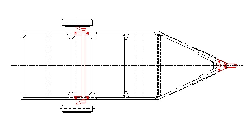
The floor is ½” plywood throughout. This is probably more than is needed, but only slightly. A scarf joint runs across the floor just behind the kink in the sidewall. A double butt strap joint could also be used (perhaps with glass tape as the butt straps), but a spline or biscuit joint is not suitable as a full strength joint is required.
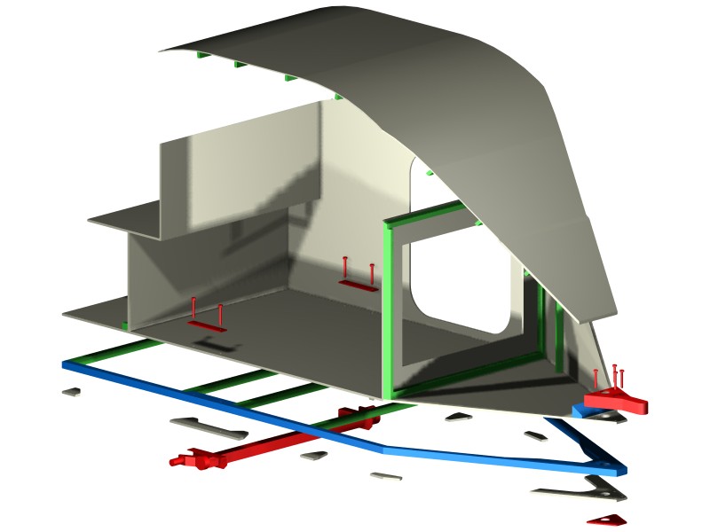
The floor is joined to the sidewalls by 2x2 framing made from oak or another hardwood. This is coloured blue on the diagrams. Hardwood is used here to provide the crush strength where the axle and coupler are bolted on and also the bending strength for the few inches by which the front of the floor/framing sticks out in front of the body sides.
Near the coupler and at the axle mounts, the framing is doubled in width, with a smooth taper at the back end of the front doubler. Other floor framing can be in softwood and framing is not required under the two bulkheads which both support the floor.
½” ply brackets are fitted under all of the floor framing joints. This is not because most of them are highly loaded but to ensure that under cyclic road loading, the joints do not start to open or crack.
The ½” ply bracket at the front extends from one side to the other, forming a solid 2.5” deep ply-hardwood-ply sandwich to which the coupler is bolted. One other piece of 2x2 hardwood is fitted on top of the floor to connect the front end of the roof directly to the floor.
Sidewalls
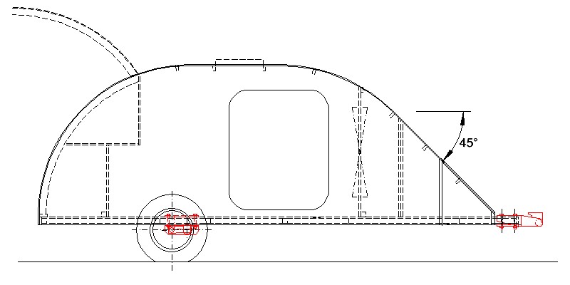
Sidewalls are made from 3/8” plywood, with two layers bonded together for the front 18” or so near the coupler where the height of the sidewall is reduced. The body is (relatively) short and high, so shear stress in the sidewalls is carrying most of the loads.
Some will ask “why not use ¾” plywood for this critical component?”. The problem there is that will double the weight and will require all joints to be twice as strong to carry the extra weight, just so the body can withstand the same accelerations as the lighter one.
Having door openings is not ideal, but they are kinda necessary….. Rounded corners to the door openings are preferred and the minimum depth of the remaining sidewall is 6” above the door and 4” below it.
To stop the sidewall from buckling, some framing will be required. One vertical frame is shown in the ‘tongue box’ in the 3/8” thick section. It is assumed that the framing around the door opening (extending from floor to roof) and internal cupboards will provide the necessary support in the main sidewall area.
To get a structural joint where the sidewall kinks, the 25 degree angle helps by providing something like an angled scarph joint – although 25 degrees is only 1 in 2.1 so hardly a good joint. The best thing would be to add glassfibre tape over the outside of the joint to provide the connection between the two panels. This would need to be a structural thickness of glass and not just the thin layer(s) that might be used as sheathing/waterproofing.
Roof
Since the body does not experience big bending loads, a fairly light roof construction is sufficient – ¼” ply made from two layers of 1/8” ply laminated together with butt straps (or glass tape) at panel joints.
Like the sidewalls, the roof is doubled in thickness near the coupler. The front end of the roof laps onto the hardwood frame fitted over the floor, to carry the load from the roof into the floor and framing.
The front and rear end of the side and roof doublers are tapered to minimise any stress concentration where they end.
Conventional roof framing, shown here as 1x2s, is sufficient.
Other Structure
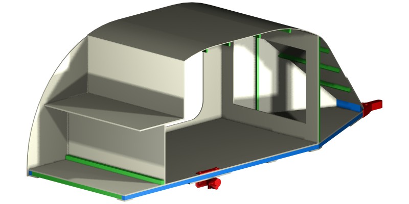
Most of the other structure does not have major structural loadings, so any lightweight construction is suitable – as long as it is all present. The stepped galley bulkhead is necessary for the torsional strength of the body and cannot be left out.
The forward bulkhead is ½” ply – a rather heavy construction, but then most of it is cut out to provide access to the tongue box.
Construction Techniques
This design assumes that epoxy is used throughout the build to give maximum joint strength. Construction techniques from boatbuilding could be used to improve joint strength and allow weight reduction, such as glass tape reinforcement at corners instead of wood framing, or epoxy fillets at lighter-loaded joints.
Similarly, some of the bracketing under the floor could be replaced by heavy glass tape in epoxy.
|
Sidewall omitted to show interior
View under floor
Exploded construction
|
|
Overhead plan view
|
View under floor |