Page 1 of 1
Bumper, taillights, motorcycle carrier

Posted:
Mon Sep 03, 2007 11:14 amby eamarquardt
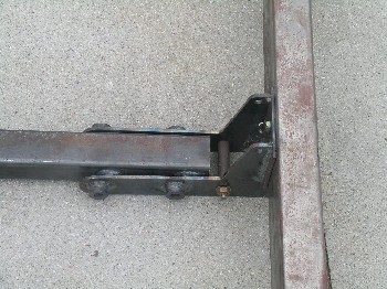
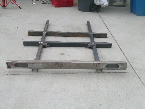
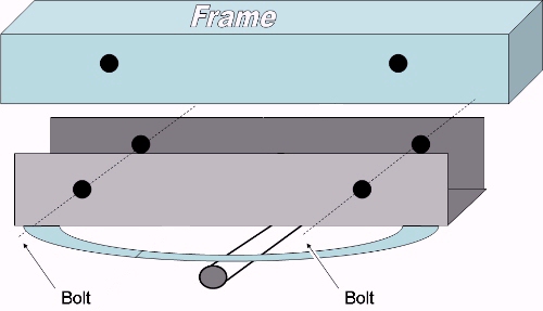
I wanted a bumper that would not impede access to the galley and I wanted to carry my Honda 200 (that I enjoy riding at 35 mph or less for a number of reasons). Here are pictures of the design I came up with. the bumper will pivot out of the way (under the trailer) when not needed by pulling a couple of pins (not in the picture). In addition, it will pull out 30 inches or so so I can set a piece of al channel across the supports to carry my motorcycle. Also visible are the cutouts for the led tail lights that will be installed (making sure they are high enough to meet the federal regs.
Cheers,
Gus
Posted:
Tue Sep 04, 2007 9:03 pmby Sam I am
Looks nice and sturdy, Gus! Very clever design!
I have a couple of concerns though:
1. Will the weight of the Honda back there reduce your tongue weight too much?
2. With the lights in the bumper you'll need an extra 30" of wire that might need to be confined somehow so as not to hang down and drag on the road if you don't carry the bike. Or will the bike always be there when towing?
Sam
Posted:
Wed Sep 05, 2007 2:03 amby MSG Hall
well I can't wait till it's done... I have been trying to think of a way to do this my self... I was leaning towards a rack over the tung though... please post as you go.
Oh and the wiring… put them inside the telescoping braces with that flexible plastic automotive wiring harness stuff… that would keep it from pinching/kinking and would keep it out of the way, off the ground…
Posted:
Wed Sep 05, 2007 9:40 amby Alphacarina
I'm lost!
Is the top picture the bumper, which folds down 90 degrees?
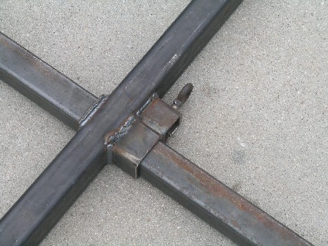
In the second picture, does unscrewing the 'wing nut' enable you to remove the frame extension from the rest of the trailer frame?
Is the bumper (with the lights) always going to stick out the back, even when you're not carrying the bike? I understand the you've probably decided to put the lights in the bumper so the bike won't impede their visibility, but that sure makes things more complicated from a wiring standpoint with the moving/disappearing bumper - Is there no other place on the tear you could put the lights?
What about tongue weight? - Either with or without the bike aboard
Interesting bit of engineering!
Don
Posted:
Wed Sep 05, 2007 11:35 amby Ken A Hood
Looks like a good design, but I would replace the screws with a hitch pin setup. They'll end up rusting on you, and get full of dirt sand and they'll seize up. All the stuff tires throw up will end up in the threads
Posted:
Wed Sep 05, 2007 9:21 pmby eamarquardt
Hi,
Thanks for the input. My axle is moveable (see my gallery) so if the tounge weight is a problem, I'll simply move the axle. Good idea about routing the wiring through the tube, I look at that as I get closer to wiring the lights. I had planned on using hitch like removeable pins on the two pins (the ones furthest back nearest the bumper) that need removing to pivot the bumper out of the way and I may install zerk (grease) fittings on the bolts the bumper pivots on. I have a dump trailer (again see gallery) with some similar parts and with an occasional squirt of grease there is no problem.
Will post further pictures as I go.
Cheers,
Eric "Gus" Marquardt
Posted:
Wed Sep 05, 2007 9:44 pmby eamarquardt
To Alphacarina,
I missed you the first time. There is no wing nut. What appears to be the wing nut is a chain link (I think chain links make nice handles) welded onto some 1/2 bar stock that is part of the latch. You can't see it but inside the short piece of tube is a spring, washer, and cotter pin that pushes the pin in to lock the long tube that moves. You pull the pin out to telescope the bumper out and the pin is pushed back in to lock it in place. You can see the pivot points for the bumper but the bolts (or pins) are not in place yet (I was too lazy to put them in for the picture). If I haven't unconfused you let me know and I'll post some more pictures sooner than later.
Cheers,
Gus
Posted:
Thu Sep 06, 2007 2:45 amby MSG Hall
Ok, so you can move the axle… this is a great idea! I wouldn’t have thought of that…
Making it work would be easy, but how are you planning to anchor the axel U bar to the frame rails? I have a couple of boat trailers with moveable axles. They bolt to the frame, two bolts on either side.
Are you going to do the same? I ask because the boat trailer is all open and the bots are easy to get to… but with the body of the TD on there I could see this being a real pain. Have you devised another method?
I can't find your gallery... could you tell me where it is?
Posted:
Thu Sep 06, 2007 4:00 amby eamarquardt
Hi,
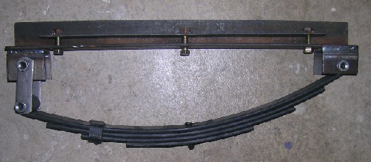
The frame will be (after a friend of mine finishes his handyman projects as he really wants to help assemble the frame) made of tubing (2X2 cross members and 2X3 runners). The spring hangers have been welded to 3/16 angle iron. The angle iron has three holes in the bottom of it and I welded three nuts to some 1X1/8 strap to make a "strap nut". When the axle is positioned where I want it, I'll mark and drill three hole on the bottom side of each of the two "runners". Then I'll push the strap nut in from the rear of the runners/trailer where the tubing is open and then insert and tighten three bolts on each side through the angle iron, through the frame tube, and into the nuts welded on the strap. I'll fabricate some removeable end caps eventually to keep water and crud out.
Once you see the assy. my humble explanation should be clear, I hope. To see my gallery, go to one of my posts and under my name is a gallery prompt. Click on it and you should bring up my gallery. Here is a picture of what I'm talking about:
If you have any more questions I'd be happy to answer them.
Cheers,
Gus
Posted:
Thu Sep 06, 2007 4:47 amby MSG Hall
this is the way my boat traile it hooked up...
easy to move...
Posted:
Thu Sep 06, 2007 9:50 amby eamarquardt
Hi again,
First, you're pretty good with CAD! I thought about this approach but the inner cross braces would limit placement of the axle, to get the u shape you have to split a piece of tubing (from experience I know that when you split tubing it warps a lot as the stresses are relieved), and when you tighten the bolts you aren't clamping on a real solid surfaces (the tube can compress, I know I'm splitting hairs on this last concern). With the angle and strap nut, placement of the axle is unlimited as the angle is only on the outside and bottom of the tube (and won't hit the cross braces as a "U" would) and when you tighten up the bolts, everything is rock solid tight against one another. I've have bad experieces (both with industrial machinery and a loose keel(#6600) on a sailboat when things aren't clamped solid so I avoid doing this whenever there is an alternative.
The best thing about building your own anything is that you "can have it your way (but I don't eat there as I'm allergic to beef, ha)".
Keep the dialog going, we can all learn from each other.
Cheers,
Gus