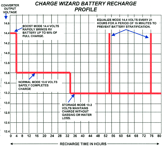
I knew I had problems yesterday as I plugged it in to charge the battery and it never came down from the 14.4 V boost at the battery (progressive Dynamics converter) until I used the disconnect switch to the battery at which point it dropped the voltage (minus battery) to 13.4V.
The electrical from the seven prong plug back to the converter is a complete unadulterated mess. I ripped it all out today!!!

I think I may have found the problem, the DC and AC side of the converter were grounded to the chassis, a big no no (big copper lugs screwed onto the aluminum chassis).
I have to run in to Toledo tomorrow to pick up more wire 6ga for the converter to the battery and two 8 ga lines for the two separate solar controllers.


 The PD has a 2 year warranty, you might be able to get PD to fix it if its broken.

 and viola everything