Could you check my wiring diagram, please?

Anything electric, AC or DC

Re: Could you check my wiring diagram, please?

Postby Martiangod » Mon Apr 23, 2012 5:41 pm

Couple revisions....

Loose the breaker on input side, not needed.
with a 1000watt inverter your not going to be running heaters and kitchen appliances.

Load on inverter will be smaller loads, Phone charger, small TV, laptop....etc

Feed the inverter charger off the 4th breaker in panel, then use the inverter to power the two cabin plugs that are not for the heater

Everything else looks pretty good,

#10 AWG on your supply line will be loads in a Tear, likely #12 would be enuff

Image
If it ain't broke, fix it till it is

Chris

Deep in the Heart of Nowhere
The topper viewtopic.php?f=50&t=58140, gone to a new home to be converted
into an ice fishing shack...FREEBIE !!! for a nice young family
The trailer viewtopic.php?f=50&t=48156
User avatar
Martiangod
500 Club
 
Posts: 856
Images: 432
Joined: Mon Jan 09, 2012 10:39 pm
Location: Peace River, Alberta

Re: Could you check my wiring diagram, please?

Postby bdosborn » Mon Apr 23, 2012 7:48 pm

A #14 awg is good for 15 amps and should be protected with a 15 amp fuse.
A #12 awg is good for 20 amps and should be protected with a 20 amp fuse.
A #10 awg is good for 30 amps and should be protected with a 30 amp fuse.

Is there any reason you want a 30 amp shore power plug? Most people do just fine with a 20A and then you don't have to mess with a plug that nobody has a receptacle for at their house.

Four 15 amp circuit breakers? Really? You might want to add up the wattage of everything you expect to run at the same time. A 20 amp circuit is good for 1920 watts and that's usually plenty for most people. Just don't run the electric heater and the electric frying pan at the same time.

The shore power wiring is required by all RV codes to be protected by a circuit breaker, located as close as practical to where the power enters the trailer. I'm not saying your trailer will blow up if you don't use one but there's some good reasons to have it.

Personally, I ran a #10 from the battery to my distribution fuse block and I've never had a problem with capacity. The main fuse should be on the other side of the switch and as close to the battery as practical. I like the Blue Sky battery terminal fuses
Fuse Linky

Bruce
2009 6.5'X11' TTT - Boxcar
All it takes is a speck of faith and a few kilowatts of sweat and grace.
Image
Boxcar Build
aVANger Build
User avatar
bdosborn
Donating Member
 
Posts: 5595
Images: 806
Joined: Wed May 05, 2004 11:10 pm
Location: CO, Littleton

Re: Could you check my wiring diagram, please?

Postby VermonTear » Fri May 04, 2012 1:10 pm

Bruce...
Chris...

Thanks for the input. I didn't see it for a week. Somehow I missed the notices of the postings and missed that there was a "Page 2" on this thread. I've been moving along soldering, but still in the midst of my wiring project. I live in fear that I will be re-incarnated as an electrician -- they say we grow to hate and prejudice what we fear and don't understand -- that's me and electricity. Oh well, got to be done.

Here's where I am so far:

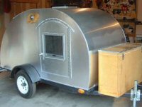
AC box and outlets are pretty much all wired. DC fixtures are also, and am wiring them back to the fuse and ground block today. The trailer side marker running lights are wired and the running light wiring is run over rooftop back to connect to the hatch (when I get it built) where the licence plate and additional stop/turn lites will be installed. I haven't got my battery compartment box built yet, but it will be under the galley counter top and the inverter will be in a separate compartment next door to it. lot of the trailer marker. I'll post some pics over in the build at the beginning of the week.

Here's my revised wiring diagram.
Image

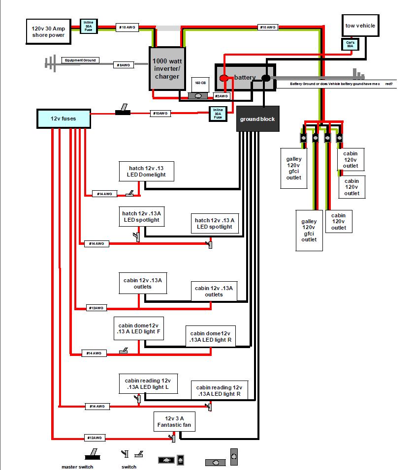
Too late for your thought, Chris, of putting the breaker for the inverter in the 4breaker box. I'm planning an inline 30A there. Will that meet the RV regs, Bruce? And yes, Bruce, I'm married to the 30A shore power cord with all that stuff (cord, chrome inlet, adapter, etc) I ordered too long ago to return.
A lot of this looks like overkill to me. The #8 AWG ground to chassis for the inverter equipment is according to the Xantex manual (and tech support) and they say I can't just connect that to the #14 ga running light ground that will be running through the tear and will be ground to the chassis -- no, I've got to drill a hole in the floor of my galley and ground it directly to the chassis (or run it another 12' up and over the roof and ground it up front!!) I'm going to have more wire than insulation in my roof!

Let me know if you see anything here that sets off alarms.

best...

Ken
Ken

My first build 12/2011: viewtopic.php?p=890137#890137
User avatar
VermonTear
Donating Member
 
Posts: 86
Images: 149
Joined: Wed Nov 16, 2011 2:07 pm
Location: Vermont
Top

Previous

Return to Electrical Secrets

Who is online

Users browsing this forum: No registered users and 1 guest