On the idea that a solar charger will charge even on a cloudy day. Current output is miniscule without full sun. Monocrystaline and polycrystaline module output will go to near zero if even a single cell is shaded. Amorphus modules do a little better at partial shading but are less efficient and don't last as well.
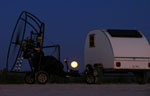
Anyway, the 43 watt solar panel on my teardrop is the only way the battery gets charged. I have no charging wire from the tow vehicle and don't haul a generator. Works great in the Oregon desert.
Q
Teardrops n Tiny Travel Trailersor t n ttt for short (tnttt.com) |
Had a new thought about charging
18 posts
• Page 2 of 2 • 1, 2
![]() by TomS » Fri Mar 25, 2005 10:29 am
by TomS » Fri Mar 25, 2005 10:29 am
I don't think solar is a viable option for me. I prefer shaded campsites. Also, a solar system with reasonable charging capacity is much more money than I care to spend.
Tom Swenson
[email protected]
[email protected]
-

TomS - 1000 Club

- Posts: 1367
- Joined: Thu Nov 18, 2004 2:06 pm
- Location: Fitchburg, MA