ultra lightweight trailer chassis concept

Ask questions about Harbor Freight trailers, or questions about building your own...

ultra lightweight trailer chassis concept

Postby kennyrayandersen » Sat Apr 22, 2023 11:01 am

This build (design exercise really, since it will be awhile before I can get to the actual build) will be done in two threads -- one for the teardrop and one for the chassis. The teardrop thread is here: https://www.tnttt.com/viewtopic.php?f=27&t=75601. In order to lower the overall weight of the build, it became apparent that none of the commercially available trailers would work due to the weight. Furthermore, bolt-together trailers will generally be heavier than one that is designed and purpose-built. This chassis will cover what is necessary to size a trailer chassis with a couple of caveats: 1) the teardrop body will be designed as a mostly self-supporting structure 2) the sizing assumes that the trailer is not poorly loaded, or overloaded. I'll discuss the options, and design choices, and explain the fundamentals of how the chassis sizing can be done by anyone who can follow the math and punch the numbers into their calculator. With patience, I don't think it is terribly difficult once it's laid out and I will be happy to answer questions. I will also touch briefly on fatigue (that won't be too deep as I'm not a fatigue specialist).

General trailer layout:
Most trailers are very overbuilt and don't consider the strength brought to the table by the teardrop cabin. Therefore much of the trailer chassis is just along for the ride -- adding weight, but not doing much of anything -- I'm gonna throw that junk away! The walls of the cabin are extremely stiff -- far stiffer even than the steal frame and we're going to take advantage of that. The overall layout will take into account the stiffness of the cabin, which means that the trailer chassis itself can be greatly reduced! You might even call it a reduced chassis or a partial chassis. It's just enough to support the the load introduction from the chassis to the cabin. The cabin will take care of the cabin (we don't need no stinking chassis! (not entirely true, but you get the point!))

tear_initial_concept_reduced.JPG
tear_initial_concept_reduced.JPG (140.93 KiB) Viewed 888 times


The chassis width is 48 inches

Aluminum is 1/3 the weight of steel. I've used steel in airplanes, but when we use it in aerospace -- it's the good stuff. I cant afford the good stuff, so lets compare hobbyist grade aluminum to mild steel:

Steel - mild steel
Yield stress = 47.7 Ksi
Ultimate stress = 58 Ksi

Aluminum 6061-T6
Yield stress = Fcy = 37 Ksi
Ultimate stress = Ftu = 41 Ksi

Aluminum 6061-T4 (T6 post weld and age hardened is approximately T4)
Yield stress = Fcy = 16 Ksi
Ultimate stress = Ftu = 26 Ksi

So, although there are stronger aluminums (more expensive), and stronger steels (more expensive), at the bottom we see that the mild steel is a little stronger than the common 6061-T6 aluminum that the consumer is likely to have access to; however, it is 3 times the weight! A quick check at On-line Metals shows for a 6 ft piece of .065 1x2 steel the price is $36.71, while the same 6061-T6 aluminum in .062 wall is 32.50! So, at the same price, 1/3 the weight and nearly the same strength - let's investigate the aluminum.
User avatar
kennyrayandersen
1000 Club
1000 Club
 
Posts: 1750
Images: 38
Joined: Sun Apr 29, 2007 10:27 pm
Location: TX

Re: ultra lightweight trailer chassis concept

Postby TimC » Sat Apr 22, 2023 12:06 pm

I like this design. I'll be watching closely.

I want to create an ultralight teardrop that my EV can pull without seriously limiting its range. I have an old boat trailer (4' wide between wheels/fenders) and I was going to convert that but maybe I'll use its axle and go this route instead. Anxious to hear from the engineer types to see the precautions of a chassis like this.

Tim
Tim
Niagara, WI
My First Benroy Teardrop Build Thread - A 5x8 Woodie - http://www.tnttt.com/viewtopic.php?f=50&t=63575
My Second Teardrop (partial) Build Thread - Started August '16 - http://www.tnttt.com/viewtopic.php?f=50&t=66939
#3 My son's Benroy Foamie team build - Started July '20 - http://www.tnttt.com/viewtopic.php?f=50&t=72877

Image
User avatar
TimC
Gold Donating Member
 
Posts: 1371
Images: 733
Joined: Sat May 23, 2015 4:15 am
Location: WI/MI border

Re: ultra lightweight trailer chassis concept

Postby QueticoBill » Sat Apr 22, 2023 6:30 pm

Yes. The walls are like trusses and a lot of stiffness. That's why I think cutting of the rails of those trailers - while weakening it as a utility trailer - is fine with a teardrop.

And your trailer design is like the Pico Light (?) that used to be in the design guide. I've admired it's design elegance.

This should be a great build thread!
QB
A tear with no name: viewtopic.php?f=50&t=67624
QueticoBill
Silver Donating Member
 
Posts: 1184
Images: 22
Joined: Sun Apr 14, 2013 7:22 am
Location: Clayton NY
Top

Re: ultra lightweight trailer chassis concept

Postby kennyrayandersen » Sat Apr 22, 2023 8:31 pm

QueticoBill wrote:Yes. The walls are like trusses and a lot of stiffness. That's why I think cutting of the rails of those trailers - while weakening it as a utility trailer - is fine with a teardrop.

And your trailer design is like the Pico Light (?) that used to be in the design guide. I've admired it's design elegance.

This should be a great build thread!


I watched a You-tuber yesterday discussing people modifying utility trailers and how it weakened them and I was disappointed that he couldn't understand the concept that the vertical walls, if attached, become the structure! Yes, the layout is very much like the Pico, but with Andrew gone (I assume he passed), and virtually none of those links working; and with no math behind any of the pictures, a general layout isn't much good because you don't know whether it will work in your particular application. I hope to show how to arrive at the sizing and discuss material and frame section choices.
User avatar
kennyrayandersen
1000 Club
1000 Club
 
Posts: 1750
Images: 38
Joined: Sun Apr 29, 2007 10:27 pm
Location: TX
Top

Re: ultra lightweight trailer chassis concept

Postby pchast » Sat Apr 22, 2023 8:39 pm

I am not a structural engineer.... However, I'd like to suggest the addition of a length of angle iron to catch the front of the cabin and spread out the point loading. This will improve the bearing of the cabin on the two pieces of tongue. It will protect the integrity of that junction.
:thinking:

I'll be watching your design with great interest. :D
pchast
Platinum Donating Member
 
Posts: 2027
Images: 97
Joined: Mon Jan 28, 2013 5:47 pm
Location: Athens, NY
Top

Re: ultra lightweight trailer chassis concept

Postby kennyrayandersen » Sat Apr 22, 2023 8:42 pm

TimC wrote:I like this design. I'll be watching closely.

I want to create an ultralight teardrop that my EV can pull without seriously limiting its range. I have an old boat trailer (4' wide between wheels/fenders) and I was going to convert that but maybe I'll use its axle and go this route instead. Anxious to hear from the engineer types to see the precautions of a chassis like this.

Tim


I think there is a real need to build lightweight and EVs is certainly an area with huge repercussions for tow weight. I recently watched a video of a Ford F-150 Lightning doing some light (maybe medium - 6000 lb) towing and it made me think that they shouldn't have bothered - they got less than 100 miles! Keeping the weight down, and the teardrop in the aerodynamic shadow of the tow vehicle (teardrop should be both narrower and as short or shorter than the tow vehicle) would go a LONG way in making towing a teardrop behind an EV practical.
User avatar
kennyrayandersen
1000 Club
1000 Club
 
Posts: 1750
Images: 38
Joined: Sun Apr 29, 2007 10:27 pm
Location: TX
Top

Re: ultra lightweight trailer chassis concept

Postby kennyrayandersen » Sat Apr 22, 2023 8:52 pm

pchast wrote:I am not a structural engineer.... However, I'd like to suggest the addition of a length of angle iron to catch the front of the cabin and spread out the point loading. This will improve the bearing of the cabin on the two pieces of tongue. It will protect the integrity of that junction.
:thinking:

I'll be watching your design with great interest. :D


Ah, broughhaha, haha! The trailer floor will have the very cross-member of which you speak! So, part of this exercise will be to eliminate the redundancy between the trailer and the cabin! :twisted: But this is actually a very good suggestion. However, after having run the numbers a bit, I'm pretty confident that the trailer can be made from aluminum and we wouldn't want to put any welds, or unnecessary holes in the trailer frame, so attaching that member on the trailer would pose some design challenges. With aluminum -- especially heat-treated aluminum -- we don't want to introduce any unnecessary stress concentrations (Kt) because it would cause fatigue issues, or welds in critical areas as you lose the heat-treated strength in the weld zone. Calculations to follow!
User avatar
kennyrayandersen
1000 Club
1000 Club
 
Posts: 1750
Images: 38
Joined: Sun Apr 29, 2007 10:27 pm
Location: TX
Top

Re: ultra lightweight trailer chassis concept

Postby kennyrayandersen » Sat Apr 22, 2023 11:22 pm

Numbers:

First we have to establish the design/analysis criteria, and the environment

Typically on-road (we'll hereafter refer to this as over the road (OTR)) vehicles and trailers are designed to 3gs and off-road (OR) vehicles and trailers are designed to 5gs - we will consider those Design Limit loads (DLL) (maximum loads the structure would ever see during it's lifetime). We also generally use an ultimate load factor of 1.5 to arrive at the Design Ultimate Load (DUL). The criteria is no yield at DLL, and no failure at DUL.

Let's also make some assumptions about the teardrop and introduce some dimensions based on the design goals. For now -- let's set the weight at no more than 300 lb (and hopefully we will be under that significantly). The 1963 FIAT 500 is 52 in. wide, but the Smart fortwo is 60 inches wide, so in order to clear the fortwo there should be somewhere in the neighborhood of 30 inches of clearance. so, the distance we need is from the ball (the load to the tongue is introduced at the ball) to where the cabin intersects the trailer. If your cabin curves aft at the front bottom, it's critical to use the intersection of cabin and frame rather than the distance to the from of the cabin. In my cabin design I brought the front straight down for two reasons 1) it makes the front of the cabin stiffer and stronger because there is a large vertical section to react the loads, and 2) it reduces the moment arm in the tongue of the frame, and so reduces the stress in the frame. That might not be a showstopper, but in any case the right dimension needs to be used in the calculations.

First let's pick a material. Since we are shooting for lightweight, let's pick aluminum, and the most readily available and at a decent price is 6061-T6. Furthermore, 6061 is a weldable aluminum alloy. The properties are:

E, Young's Modulus = 9.9E6
Fcy = compression yield = 37 Ksi
Ftu = Ultimate allowable tension stress = 41 Ksi

For weld zones (we'll talk about those later) the material becomes annealed, but 6061 quickly age-hardens over a few weeks and months to the T4 condition. So, for heat affected areas we will use the T4 properties:

E, Young's Modulus = 9.9E6
Fcy = compression yield = 16 Ksi
Ftu = Ultimate allowable tension stress = 26 Ksi

(When we look at the difference in properties between the T6 and T4 conditions, it tells us is that we don't want to do ANY welding in a stress critical area!)

Since we set the weight of the teardrop at 300 lb, we can use a percentage of that weight to apply to the coupler at the ball .I think a fair target would be 15% of the total trailer weight, but lets be on the safe side and use 20%. We use the letter P for load (because we use L for something else!)

P = .20 * 300 lb = 60 lb

Now we calculate the maximum moment in the tongue area which is where the front of the cabin meets the frame

L = 30 inches (tongue length from ball to cabin)

M = L * P = 60 lb * 30 inches = 1800 in-lbs

Inertia is the beams resistance to bending. Inertia for a rectangular section is:

I = 1/12bh^3 -- that is for a solid section where b is the width and h is the height.

For a hollow section we can calculate what it would be for a solid section and then subtract the hole from it. Our equation then becomes:

I = 1/12(b_outer * h_outer^3 - b_inner * h_inner^3)

Alternately sometimes you can find I listed for a particular beam section - the units are in^4

The astute observer will see that the h term is cubed! So, a 1x2 section, for instance, is much stronger standing up than lying down! We'll stand ours up!

Let's start by using a 1x2 aluminum section with a .062 wall, standing vertically!

I = 1/12 ((1)*(2)^3 - (.875)*(1.875)^3) and since we have 2 frame members the equation becomes:

I = 1/6 ((1)*(2)^3 - (.875)*(1.875)^3) = .372 in^4


The bending stress is: F_b = Mc/I where M is the Moment, c is the distance from the section centroid to the outer fiber (for symmetric sections it is just 1/2 the height), and I is the Inertia

The original moment was 1800 in-lb, but that is at 1g. For OTR we'll use 3g, and for OR we'll use 5g

M_OTR = 1800 in-lb *3 - 5400 in-lb

M_OR = 1800 in-lb *3 = 9000 in-lbs

plugging in the numbers into the bending stress equation: fb = M*c/I

fb OTR = (5400 in-lb * 1in)/.372 in^4 = 14.5 Ksi

M.S. = margin of safety = F_allowable/f_actual - 1

M.S yield_OTR = 37 Ksi/14.5 Ksi - 1 = +1.55 (yield criteria is met - anything above +0.00 is OK)

Check for no failure at ultimate load

Ultimate f_bending = f_bending DLL * 1.5 = 14.5 * 1.5 = 21.8 Ksi

M.S. ult otr = 41 Ksi/21.8 Ksi = +.88 (ultimate criteria is met)

(note that for ductile materials that have been heat-treated, the ultimate stress check is usually the critical one, but with annealed 6061 the yield check is critical)

Lets check whether the OR loading is OK

f_b OR = 9000 in lb * 1/.372 = 24.2 Ksi Limit, 36.3 Ultimate

M.S. OR Lim = 37/24.2 - 1 = +.52 (Yield check is satidfied)

M.S OR Ult = 41/36.3 - 1 = +.13 (Ultimate check is satisfied)

So, for static loading, over-the-road or off-road, the strength requirement is met.

We're talking about aluminum here though, right? How about fatigue?

When aluminum is working hard enough there is damage being done with every load cycle. The higher the stress, the more damage is done with every cycle. If the stress is very high, you might only get a few cycles before failure; however, at low stress there is little or no damage being done. The key to a long fatigue life is to limit the operating stress to one low enough that you aren't doing significant damage when it is repeatedly loaded. For 6061-T6 aluminum the endurance limit is 14000 psi, which assumes: 500,000,000 cycles completely reversed stress (this assumes an stress ratio of -1 i.e. fully reversible). Because I g-loading, OTR or OR, is almost exactly in one direction our load does not fully reverse, and that makes a huge different. We can assume that our load gets applied, and then never goes below zero - that gives us a stress ratio of zero (non-reversing load).

Lets look at the fatigue endurance curves

6061 s-n curve.jpg
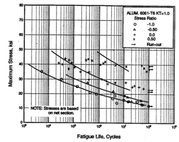
6061 s-n curve.jpg (88.15 KiB) Viewed 791 times


The plus symbol is the curve were looking at (stress ratio of zero) and the endurance limit is just a bit above 20 KSI for repeated loading for which stresses below that will result in an infinite life. So, we'll use that as our stress to stay under for Limit loading. This is a bit conservative and we are not realizing limit stress every time the frame is loaded; but, if we set the stress this low at limit load, then we should be way OK for fatigue. Note that this assumes that we haven introduced any holes or welds in a stress critical area.

Let's look at our limit stresses again:

fb OTR = 14.5 Ksi Limit (below 20 Ksi, so it looks like fatigue won't be a problem unless we screw up some design feature!)

fb OR = 24.2 Ksi Limit (this is above 20 KSI, so it doesn't meet the fatigue cut-off for a infinite life)

Therefore, so far, the 1x2x.062 rectangular section should work for the frame (we will do other checks to confirm) in the OTR case, but wouldn't be acceptable for off-roading.

So, what does this tell us? For a OTR design the aluminum .062 wall section should work fine, but for off-road this section wouldn't be recommended. The designer of an off-road version would then have a choice here: 1) use aluminum, but change the wall thickness to .12 in., 2) change the .062 wall aluminum section to 2x2, or 3) use a 1x2 .062 section made from steel, which would carry a smaller weight penalty compared to an aluminum section that now grows to the next size up and doesn't have the same fatigue considerations.

This concludes the initial check. More checks to follow.
User avatar
kennyrayandersen
1000 Club
1000 Club
 
Posts: 1750
Images: 38
Joined: Sun Apr 29, 2007 10:27 pm
Location: TX
Top

Re: ultra lightweight trailer chassis concept

Postby kennyrayandersen » Sun Apr 23, 2023 6:41 am

Strength Checks continuing:

Weld areas have lower allowables, so the next check would be aft of the ball where the A-frame comes together and is welded. assume T6 heat treat is lost and the material has annealed and been age-hardened to the T4 condition.

(Properties listed in first post)

Since the moment is linear we can ratio the stress. check at 16 in. from the ball

16/x=30/14.5

Fb@ 16 in = x = (16*14.5)/30 = 7.7 Ksai Limit, 11.6 ultimate

Use properties from 6061-T4

M.S. Limit = 16/7.7 -1 = +1.08 (as stated earlier the yield margin is critical in the weld area) (OK for Limit)

M.S. Ultimate = 26/11.6 -1 = +1.24 (OK for ultimate loading)

The endurance limit for aluminum is approximately 1/2 the ultimate tensile strength, so the fatigue would be OK for here as well
User avatar
kennyrayandersen
1000 Club
1000 Club
 
Posts: 1750
Images: 38
Joined: Sun Apr 29, 2007 10:27 pm
Location: TX
Top

Re: ultra lightweight trailer chassis concept

Postby kennyrayandersen » Sun Apr 23, 2023 7:29 am

Let's check to see if the attachment of the coupler is OK

sorry for the unsophisticated art...

coupler - small.JPG
coupler - small.JPG (146.98 KiB) Viewed 758 times


The fastener going through the side of the frame section are 3/8 in dia

When we are calculating the reactions on a beam, we typically sum the forces which must equal zero (else it would be flinging in space), and we can sum the moments, which also must be equal to zero (else flinging)

Going back to our ball load, it was 60 lb at 1g

Sum M = 0

Moments that make clockwise are negative, and moments that are CCW positive. For convenience we will sum the moments about R2 (refer to diagram)

P * 7.5 in - R1 * 2.25 in = 0

Solving for R1 (reaction at first bolt) = 5.25*60/2.25 = -200 lb

At limit load (3g) we get -600 lb

Note that the bolt goes all the way through the section and the bolt is in double shear so that each side of the frame section is reacting 1/2 of the load; therefore:

P_bolt_shear = -600 lb / 2 = -300 lb This is a trivial load for a 3/8 inch fastener

We should also check the second bolt (although I already know it will be less critical)

This time we will use summation of forces = 0

60 - 200 + R2 = 0

Solve for R2

R2 = 200 - 60 = 140 lb @1g

Since this bolt load is less than the first bot at R1 is it OK by comparison

Let's check bearing stress in the aluminum

Area_bearing = t * D where t = material thickness and D = bolt diameter

A_br = .062 * .375 = .0232 in^2

f_br_yield = 300 lb / .0232 in^2 = 12.9 Ksi

f_br_ult = P/A_br = 450 lb / .0232 in^2 = 19.4 Ksi

F_br_yield = 56 Ksi

Fbr_ult = 88 Ksi

M.S. br ult = 88 / 19.4 -1 = +high

Fbr_limit = 88 Ksi

M.S. br linit = 56 / 12.9 -1 = +high

Note these fasteners go through the frame section near the middle (close to the centroid) where the stress is very low so that it doesn't affect the margin we already calculated for the frame section

Coupler attachment is OK


P
User avatar
kennyrayandersen
1000 Club
1000 Club
 
Posts: 1750
Images: 38
Joined: Sun Apr 29, 2007 10:27 pm
Location: TX
Top

Re: ultra lightweight trailer chassis concept

Postby Ottsville » Sun Apr 23, 2023 8:17 am

TimC wrote:I like this design. I'll be watching closely.

I want to create an ultralight teardrop that my EV can pull without seriously limiting its range. I have an old boat trailer (4' wide between wheels/fenders) and I was going to convert that but maybe I'll use its axle and go this route instead. Anxious to hear from the engineer types to see the precautions of a chassis like this.

Tim


This trailer design is not new - there's some OLD posts around here with the simple A style chassis.
Ottsville
The 300 Club
 
Posts: 320
Images: 4
Joined: Tue May 08, 2018 2:19 am
Location: Virginia
Top

Re: ultra lightweight trailer chassis concept

Postby kennyrayandersen » Sun Apr 23, 2023 8:44 am

That pretty much covers the loads expected whilst going down the road. There is one other condition that I considered and that what about when both people are in the cabin? The critical condition is likely when they are both entering into the cabin at the door, and let's say they plop them selves down in the doorways simultaneously.

Assumptions:

2- people @ 200 lb each

1g plus 1.5 dynamic magnification factor

people_loads - reduced.JPG
people_loads - reduced.JPG (91.39 KiB) Viewed 721 times


We need to calculate the load on the ball

The 2 reaction points are at the ball and at the wheels (see figure above)

Summing the moments as we did before about point R2

-R1 * 78 in + 400 lb * (78 in - 54 in) = 0

Solve for R1 = 400*24/78 = 123 lb

plus we have already the static load from the trailer itself (remember that 60 lb load on the ball?)

P_ball_total = 123 lb + 60 lb = 183 lb (this is at 1 g)

Moment at the cabin and trailer frame intersect = 183 lb * 30 in = 5490 in-lb

Fb_lim = 5490*1/.372 = 14.8 Ksi

Adding the dynamic magnification factor (this is really quire conservative as it requires both people to plop particularly hard at the same time)

Fb_lim_final = 14.8 *1.5 = 22.1 Ksi

M.S. Lim = 37/22.1 - 1 = +.67 (Limit check is OK)

M.S Ult = 41/(22.1*1.5) -1 = +.23 (Ultimate check is OK)

This would also lower the coupler margin just a bit, but because those margins are high it's not an issue

People loads are OK
User avatar
kennyrayandersen
1000 Club
1000 Club
 
Posts: 1750
Images: 38
Joined: Sun Apr 29, 2007 10:27 pm
Location: TX
Top

Re: ultra lightweight trailer chassis concept

Postby kennyrayandersen » Sun Apr 23, 2023 8:50 am

Ottsville wrote:
TimC wrote:I like this design. I'll be watching closely.

I want to create an ultralight teardrop that my EV can pull without seriously limiting its range. I have an old boat trailer (4' wide between wheels/fenders) and I was going to convert that but maybe I'll use its axle and go this route instead. Anxious to hear from the engineer types to see the precautions of a chassis like this.

Tim


This trailer design is not new - there's some OLD posts around here with the simple A style chassis.


Yes, I already addressed that. It's very similar to the Pico frame, but there no numbers or analysis to support the sizing so this is about figuring our how to size the frame (any frame really). The principles would apply to any frame -- not just an A-frame. I chose the A-frame because I believe that to be the lightest weight configuration and I need a very light teardrop.
User avatar
kennyrayandersen
1000 Club
1000 Club
 
Posts: 1750
Images: 38
Joined: Sun Apr 29, 2007 10:27 pm
Location: TX
Top

Re: ultra lightweight trailer chassis concept

Postby TimC » Sun Apr 23, 2023 9:42 am

Just wondering if instead of an A frame it was a U frame. Possibly supporting two to three feet of the front of the cabin.

More complicated obviously requiring some bending.
Tim
Niagara, WI
My First Benroy Teardrop Build Thread - A 5x8 Woodie - http://www.tnttt.com/viewtopic.php?f=50&t=63575
My Second Teardrop (partial) Build Thread - Started August '16 - http://www.tnttt.com/viewtopic.php?f=50&t=66939
#3 My son's Benroy Foamie team build - Started July '20 - http://www.tnttt.com/viewtopic.php?f=50&t=72877

Image
User avatar
TimC
Gold Donating Member
 
Posts: 1371
Images: 733
Joined: Sat May 23, 2015 4:15 am
Location: WI/MI border
Top

Re: ultra lightweight trailer chassis concept

Postby kennyrayandersen » Sun Apr 23, 2023 9:58 am

TimC wrote:Just wondering if instead of an A frame it was a U frame. Possibly supporting two to three feet of the front of the cabin.

More complicated obviously requiring some bending.


U's, not being straight create additional torsional moments when loaded. It might well work, but there is a cross member in the floor, shown on the cabin thread (as opposed to the frame thread). And I think you are right about the forming challenges. I think, in the end, the cabin is still supported at 3 points -- the ball, and each of the 2 wheels. If the cabin is self-supporting and has a good attachment to the frame, I think it should work out OK. The original layout, by Andrew for the Pico also had the A-frame configuration, and I incidentally just spotted a teardrop that is currently being manufactured with an A-frame trailer. I haven't show the weight calculations, but right now at .062 wall the frame weight (not including suspension or coupler is just over 11 lb. If you go up to .125 in wall thickness it's still only 17.4 lb! With the torsion 1/2 axles this should be a very light trailer!
User avatar
kennyrayandersen
1000 Club
1000 Club
 
Posts: 1750
Images: 38
Joined: Sun Apr 29, 2007 10:27 pm
Location: TX
Top

Next

Return to Trailer and Chassis Secrets

Who is online

Users browsing this forum: No registered users and 30 guests