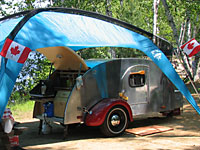
Del's canned ham build

Design & Construction of anything that's not a teardrop e.g. Grasshoppers or Sunspots

Postby del » Mon Sep 22, 2008 11:48 am

angib wrote:Yes, the orange lines are ribs - and also the joints between the 16 pieces of ply that make up the rolled edge.

I've made the shape of the ribs circular as the skin can bend most easily to that shape. If the ribs were elliptical, the side skin would curve right round onto the top/bottom/front/rear. This would look wonderful, but the radius at the end would be something like 1", so nothing would bend round that.

Here's a sketch of how I see this being built. This is a view looking backwards through the top (side/roof) corner, but the side panel would be built lying on flat building base/surface, using your (red) outer ring frame as a base.

Each orange rib then (a) provides reinforcement to the assembly when finished, but also (b) acts as a jig during assembly to support the inner ring frame the right distance off the building base.

Image

After assembly is competed, the excess bit of each rib is cut off - not easy, as access is poor, but then life isn't easy......

Does that make sense?

Andrew
Yes is makes sense, and I do believe I can build that.

Thank you very much, del.
User avatar
del
5000 Club
5000 Club
 
Posts: 5674
Images: 410
Joined: Fri Sep 08, 2006 3:27 pm
Location: washington, yakima but tell Mary K Fairbanks

Postby angib » Mon Sep 22, 2008 6:03 pm

It will be interesting to see if this increases, or reduces, confusion or whether you say "yeah, that's obvious".

This is what the side wall assembly would look like before any of the outer skin has been added - the outer and inner ring frames held up on the ribs. There are some extra ribs along the bottom to hold the side wall shape and there would also be wall studs and noggins (are those words used in the US?) inside the inner ring frame to suit the door and window openings.

Image

Clearly it would be a good idea to move the door opening, or adjust the top curve, so that the door opening fell in the parallel section of side wall.

Thinking some more about how the side skin can be bent in plywood, I realised that some of the 'petals' around the edge could be bent from the flat side skin ply. In theory all of them could be, but the accuracy of laying out and cutting the slits between the 'petals' would have to be impossibly high.

So I end up with five 8x4 sheets of (green) side skin ply that run from top to bottom and ten individual (purple) 'petals' that are cut and fitted separately. I have arbitrarily sized those so that they are a little under 24" wide, so they fit nicely in 4x8 sheets.

Image

Andrew
User avatar
angib
5000 Club
5000 Club
 
Posts: 5783
Images: 231
Joined: Fri Apr 30, 2004 2:04 pm
Location: (Olde) England

Postby Alan Wood » Mon Sep 22, 2008 11:22 pm

Del:
Another possible method just occured to me. If for the curved panels in Andrews idea are replaced with foam sheets the constant curve would be faiirly easy to get. First rough it out being carefull no to get too close to the finished curve. Then a template lined with sandpaper would be runaround till the desired shape was there.
Alan Wood
User avatar
Alan Wood
5000 Club
5000 Club
 
Posts: 5130
Images: 2
Joined: Tue Feb 07, 2006 1:26 am
Location: Sacramento California
Top

Postby del » Tue Sep 23, 2008 12:05 am

angib wrote:It will be interesting to see if this increases, or reduces, confusion or whether you say "yeah, that's obvious".

This is what the side wall assembly would look like before any of the outer skin has been added - the outer and inner ring frames held up on the ribs. There are some extra ribs along the bottom to hold the side wall shape and there would also be wall studs and noggins (are those words used in the US?) inside the inner ring frame to suit the door and window openings.

The frame work for the door will determine placement for at least four pieces (two at the top, two more at the bottom), and four more in the door. My current thought is build the wall with bracing included for the door, then cut out the door (just like the last time, without the spring back) As far as noggin used with frame work, that must be an English thing, studs are 2 x 4s in many houses.
angib wrote:Image

Clearly it would be a good idea to move the door opening, or adjust the top curve, so that the door opening fell in the parallel section of side wall.

Thinking some more about how the side skin can be bent in plywood, I realised that some of the 'petals' around the edge could be bent from the flat side skin ply.

Would you say this has more or less of a curve then the roswell side walls (the roswell tested the bend ability of the ply this way, rotating it 90 degrees would mean I could safely bend it further.)?
angib wrote: In theory all of them could be, but the accuracy of laying out and cutting the slits between the 'petals' would have to be impossibly high.

So I end up with five 8x4 sheets of (green) side skin ply that run from top to bottom and ten individual (purple) 'petals' that are cut and fitted separately. I have arbitrarily sized those so that they are a little under 24" wide, so they fit nicely in 4x8 sheets.

Image

Andrew

del
Last edited by del on Tue Sep 23, 2008 12:10 am, edited 1 time in total.
User avatar
del
5000 Club
5000 Club
 
Posts: 5674
Images: 410
Joined: Fri Sep 08, 2006 3:27 pm
Location: washington, yakima but tell Mary K Fairbanks
Top

Postby del » Tue Sep 23, 2008 12:09 am

Alan Wood wrote:Del:
Another possible method just occured to me. If for the curved panels in Andrews idea are replaced with foam sheets the constant curve would be faiirly easy to get. First rough it out being carefull no to get too close to the finished curve. Then a template lined with sandpaper would be runaround till the desired shape was there.
Alan are you coming over to sand like this?

del
User avatar
del
5000 Club
5000 Club
 
Posts: 5674
Images: 410
Joined: Fri Sep 08, 2006 3:27 pm
Location: washington, yakima but tell Mary K Fairbanks
Top

Postby Alan Wood » Tue Sep 23, 2008 1:07 am

del wrote:
Alan Wood wrote:Del:
Another possible method just occured to me. If for the curved panels in Andrews idea are replaced with foam sheets the constant curve would be faiirly easy to get. First rough it out being carefull no to get too close to the finished curve. Then a template lined with sandpaper would be runaround till the desired shape was there.
Alan are you coming over to sand like this?

del


Del, I forgot to mention fiberglassing afterwards. Anyway I'm pretty sure that with it would go smoothly.
Alan Wood
User avatar
Alan Wood
5000 Club
5000 Club
 
Posts: 5130
Images: 2
Joined: Tue Feb 07, 2006 1:26 am
Location: Sacramento California
Top

Postby del » Tue Sep 23, 2008 1:12 am

Alan Wood wrote:
del wrote:
Alan Wood wrote:Del:
Another possible method just occured to me. If for the curved panels in Andrews idea are replaced with foam sheets the constant curve would be faiirly easy to get. First rough it out being carefull no to get too close to the finished curve. Then a template lined with sandpaper would be runaround till the desired shape was there.
Alan are you coming over to sand like this?

del


Del, I forgot to mention fiberglassing afterwards. Anyway I'm pretty sure that with it would go smoothly.
I had guessed the fiberglass part, it was the running around in circles with sand paper that got me.

del
User avatar
del
5000 Club
5000 Club
 
Posts: 5674
Images: 410
Joined: Fri Sep 08, 2006 3:27 pm
Location: washington, yakima but tell Mary K Fairbanks
Top

Postby Alan Wood » Tue Sep 23, 2008 2:14 am

del wrote:
Alan Wood wrote:
del wrote:
Alan Wood wrote:Del:
Another possible method just occured to me. If for the curved panels in Andrews idea are replaced with foam sheets the constant curve would be faiirly easy to get. First rough it out being carefull no to get too close to the finished curve. Then a template lined with sandpaper would be runaround till the desired shape was there.
Alan are you coming over to sand like this?

del


Del, I forgot to mention fiberglassing afterwards. Anyway I'm pretty sure that with it would go smoothly.
I had guessed the fiberglass part, it was the running around in circles with sand paper that got me.

del

The trick would be carefully rough cutting it.
Alan Wood
User avatar
Alan Wood
5000 Club
5000 Club
 
Posts: 5130
Images: 2
Joined: Tue Feb 07, 2006 1:26 am
Location: Sacramento California
Top

Postby angib » Wed Sep 24, 2008 4:24 pm

del wrote:Would you say this has more or less of a curve then the roswell side walls (the roswell tested the bend ability of the ply this way, rotating it 90 degrees would mean I could safely bend it further.)?

The lower Roswell side walls have a radius of 26" and this bulge has a radius of 21.75", so it's a bit tighter. I presume on your Roswell the 8ft dimension in the ply went from top to bottom - this would be the same.

And if you want to use this, I have to start again - all this SMV-ish stuff has been lost in a hard disc crash I've just had, as it's since the backup I did last week!

Andrew
User avatar
angib
5000 Club
5000 Club
 
Posts: 5783
Images: 231
Joined: Fri Apr 30, 2004 2:04 pm
Location: (Olde) England
Top

Postby Cliffmeister2000 » Wed Sep 24, 2008 6:51 pm

Hard discs, they are the epitomy of O'Toole's law.

O'Toole's Law: "Murphy is an optimist."
God Bless

Cliff

♥God. ♥People.
1 John 4:9-11

My Teardrop build pictures
User avatar
Cliffmeister2000
Titanium Donating Member
 
Posts: 3622
Images: 157
Joined: Thu Jul 26, 2007 10:18 pm
Location: Phoenix, AZ
Top

Postby del » Thu Sep 25, 2008 2:00 am

angib wrote:
del wrote:Would you say this has more or less of a curve then the roswell side walls (the roswell tested the bend ability of the ply this way, rotating it 90 degrees would mean I could safely bend it further.)?

The lower Roswell side walls have a radius of 26" and this bulge has a radius of 21.75", so it's a bit tighter. I presume on your Roswell the 8ft dimension in the ply went from top to bottom - this would be the same.

And if you want to use this, I have to start again - all this SMV-ish stuff has been lost in a hard disc crash I've just had, as it's since the backup I did last week!

Andrew

Andrew
Hard drive crash, the thought of it makes me shutter, sorry to hear about it. On the roswell I did install the ply 8' top to bottom, and it was pushing how far I could bend the ply that direction. There is a direction I can bend the ply safely, and the curved bits need to be ordinated accordingly. Which makes me think skinning the flat, and curved bits separately.
Image
The one I am curios about is dimensions on, is this piece. Seeing I have to produce at least 24 per side.

del
User avatar
del
5000 Club
5000 Club
 
Posts: 5674
Images: 410
Joined: Fri Sep 08, 2006 3:27 pm
Location: washington, yakima but tell Mary K Fairbanks
Top

Postby Alan Wood » Sat Sep 27, 2008 4:37 am

Del,
Another way for you to shoot down or not.
Strip plank the area that Angib says to bend plywood around ie the compound curved area. It should work out to be the same width etc all the way around. This simpifies things imensly. It would of course look strange if not painted. Hm...
By the way please stop this quest for the most dificult build. Your making me think of building the 47 roswell in aluminum or it's follow on the much larger 47 Maury Island. Compared to what your doing it's almost a piece of cake! ;)
Alan Wood
User avatar
Alan Wood
5000 Club
5000 Club
 
Posts: 5130
Images: 2
Joined: Tue Feb 07, 2006 1:26 am
Location: Sacramento California
Top

Postby del » Sat Sep 27, 2008 2:09 pm

Alan Wood wrote:Del,
Another way for you to shoot down or not.
Strip plank the area that Angib says to bend plywood around ie the compound curved area. It should work out to be the same width etc all the way around. This simpifies things imensly. It would of course look strange if not painted. Hm...
By the way please stop this quest for the most dificult build. Your making me think of building the 47 roswell in aluminum or it's follow on the much larger 47 Maury Island. Compared to what your doing it's almost a piece of cake! ;)
The skin on this trailer will be a 1/8" thick, planks that size? The roswell I believe was intended to be skinned in aluminum, the thought of polishing makes me prefer paint. Now whats this 47 Maury island? Does it have a boat on top? :twisted:

del
User avatar
del
5000 Club
5000 Club
 
Posts: 5674
Images: 410
Joined: Fri Sep 08, 2006 3:27 pm
Location: washington, yakima but tell Mary K Fairbanks
Top

Postby del » Sat Sep 27, 2008 2:17 pm

I took a delivery in today.
Image
Tucked in its little hidey hole.
Image
Gears are turning.
Image
I wish these cross members were six inches further forward, may still.

del
User avatar
del
5000 Club
5000 Club
 
Posts: 5674
Images: 410
Joined: Fri Sep 08, 2006 3:27 pm
Location: washington, yakima but tell Mary K Fairbanks
Top

Postby Alan Wood » Sat Sep 27, 2008 3:26 pm

del wrote:
Alan Wood wrote:Del,
Another way for you to shoot down or not.
Strip plank the area that Angib says to bend plywood around ie the compound curved area. It should work out to be the same width etc all the way around. This simpifies things imensly. It would of course look strange if not painted. Hm...
By the way please stop this quest for the most dificult build. Your making me think of building the 47 roswell in aluminum or it's follow on the much larger 47 Maury Island. Compared to what your doing it's almost a piece of cake! ;)
The skin on this trailer will be a 1/8" thick, planks that size? The roswell I believe was intended to be skinned in aluminum, the thought of polishing makes me prefer paint. Now whats this 47 Maury island? Does it have a boat on top? :twisted:

del


Hm I don't think that 1/8th inch would work maybe 3/8ths...

The pictures I have seen of the 47 Maury Island were a bit fuzzy. I don't think that the top was a boat but with aliens involved who knows.
;) Alan Wood
Alan Wood
User avatar
Alan Wood
5000 Club
5000 Club
 
Posts: 5130
Images: 2
Joined: Tue Feb 07, 2006 1:26 am
Location: Sacramento California
Top

PreviousNext

Return to Non-traditional Designs

Who is online

Users browsing this forum: No registered users and 6 guests