Travel trailer with slide out build

...ask your questions in the appropriate forums BUT document your build here...preferably in a single thread...dates for updates, are appreciated....

Travel trailer with slide out build

Postby Dmanrick » Fri Apr 01, 2011 7:19 pm

Well a while ago I decided to build a pop up toy hauler. I got almost all of the outside done and all of the canvas done and then realized that I had a lot of money in something that wasn't going to be used but maybe 3 or 4 times for what it was designed for in it's entire life.

After reading Fromeo's build about a dozen times I decided to strip the thing down to the frame and start over and built one based on his.

I will just barely show the trailer build because it is outlined pretty good in this topic http://www.tnttt.com/viewtopic.php?t=40011&sid=6926ea0bf82553904b413d95224e5583

I wanted this one to be a bit different. I wanted a slide out. I don't mind a manual crank one so I got to designing in my head and by trial and error. The solution I came up with is pretty economical, easy to build and easy to operate. It is also completely adjustable and serviceable. Only the couch will slide out so it isn't like it would be the whole side.

So I guess let's get started.

Here is a few pics of the basic trailer build.

Image

Image

Image

Here's what it looked like after paint. My progress after that except for the canvas was documented in the other topic but this is basically what it looked like after I stripped everything off to start this build. Well almost. I did cut off all of the popup components. I braced the top pretty good to hold the quads good and sturdy.

Image

Image


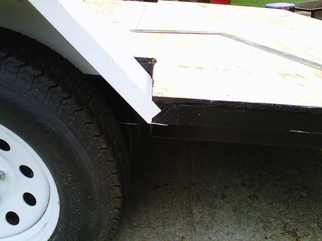
This is basically the slide out section after installing but before adjusting. I took it all apart for paint so I didn't spend any time adjusting it.

Image

Here's how I got there. Basically it rides on bearings on the outside, it has bearings on the bottom on the inside so the upwards pressure will ride along the bottom of square tubing on either side. To run it in and out it is simply a grade 8 piece of all thread that you can use a drill or a hand crank. The coupler nut that works it is the same size as the stabilizer jacks bolt.

This is what the outside of the 1 1/2" square tubing rolls on. These bearings are double sealed and will take over 600 pounds of radius pressure each. In between the bearings are plastic spacers.

Image

This shows the plastic caps that will finish it off.

Image

The next two pics are of the inside bearings. I just took some square tubing and drilled it and pup a pipe nipple through the holes and welded it. I guess I could have brought longer pipe nipples and cut the threads off but I didn't think about it before I did it. There is square tubing on either side of both sliding arms for these bearings to roll against. As you can see they will be easily adjustable and replaceable should there ever be a problem.

Image

Image

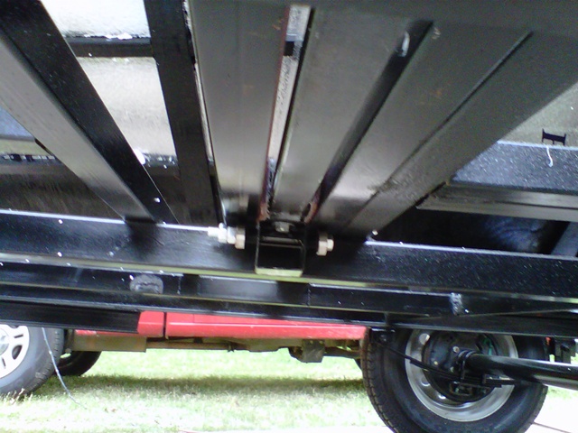
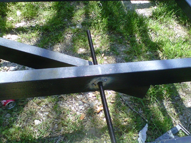
I then welded the crossbar and started on the mechanism to make it actually go in and out. I got a weld nut from McMaster Carr along with the other pieces. The weld nut allows you to weld it without screwing up the threads. Here is what it looks like both in and out of the hole.

Image

Image

On the crossbar I just welded a piece of angle, drilled a hole in it and slid the all thread through it with double nuts on either side to keep it from slipping and threaded it into the weld nut. The pic of the weld nut end is when it was tacked, not welded.

Image

Image

These pictures show how it looks slid both out and in. There were 2 men over 200 pounds standing on it and it slid in and out like butter so I'm sure it will work.

Image

Image


I don't show a pic but I did weld a piece of square tubing over the inside of the frame that cover up the all thread. First of all to help keep dirt and stuff out and second because if you use a drill, it starts wobbling pretty good in there when there gets to be more rod coming through. Not so bad when you hand crank it. There is way more bracing on this thing than it will ever need but I just didn't feel like cutting it off so I left it.

I am a lot further than this and will post more pics later and definitely before the weekend is over.
Last edited by Dmanrick on Fri Apr 01, 2011 8:23 pm, edited 2 times in total.
Dmanrick
Gold Donating Member
 
Posts: 65
Joined: Tue Sep 14, 2010 8:42 pm

Postby Gage » Fri Apr 01, 2011 7:29 pm

It would be nice if I could see the pictures. :thinking:


PS: You can prevent a question like this if you PREVIEW your post befor submitting it. Then figure out what's wrong. :yes: Never mind :oops:
Image Image Image
Remember 'Teardrop Time'.......Take your time, you don't have to have it finished NOW.
User avatar
Gage
8000 Club
8000 Club
 
Posts: 8321
Images: 28
Joined: Sat Apr 17, 2004 9:14 pm
Location: Palmdale, CA

Postby Dmanrick » Fri Apr 01, 2011 7:31 pm

Sorry. I had issues but I think all is good now. Heck, I run a big forum. You'd think I know how to do this stuff. :)
Dmanrick
Gold Donating Member
 
Posts: 65
Joined: Tue Sep 14, 2010 8:42 pm
Top

Postby Dmanrick » Fri Apr 01, 2011 10:33 pm

More...

After painting the frame we started on the floor. I decided to build a 2x2 frame under the plywood for a couple of reasons. I wanted to stick over the metal framework on each side mainly to compensate for the slide out crossbar. I framed the outside boards with 2x4's so I could let the inside rest on the metal frame and let the outside stick out 1 1/2". I also ran a 2x4 down where each plywood seam is.

Image

Here is the floor all framed up with the first sheet of 1/2" plywood on it.

Image

Here it is with all the plywood screwed down.

Image

Around the slideout, I cut the ends at a 10 degree angle. I figure when I do the seal it won't bind on it when it goes in and out. Also cutting the 1 1/2" out of it will make the slideout wall set flush with the rest of the side.

Image

Image

Here are a couple of pics with the slide out framework in various positions.

Image

Image

My dear wife and I then flipped it over to treat the underside. That was hard on her.

Image

You can see here where I had to slot just a little where the slide out arms will go since they are slightly higher than the other 1 1/2" tubing.

Image

My son in law came over for a few minutes one day so I took advantage of him being here to flip the floor back over since it was so hard on my wife. I wasn't ready for it but I did it anyway and just lifted it up one side at a time to work on it.

For the wheel wells I salvaged some aluminum sheeting from what I tore off the old part and used my brake to form them. They are 2 pieces that are pop riveted together and nailed with roofing nails on the bottom of the floor.

Image

Image

I also caulked the metal before riveting. Notice I broke a flange on the outside to easily attach them to the walls.

Image

After they were riveted, I flipped them over and put some more caulking on the inside.

Image

One side had a couple of holes that I had to patch.

Image

Here is one slid in to where it needs to be. I haven't attached them yet, just checking to make sure they fit.

Image

Image
Dmanrick
Gold Donating Member
 
Posts: 65
Joined: Tue Sep 14, 2010 8:42 pm
Top

Postby myoung » Fri Apr 01, 2011 10:57 pm

This will be fun to follow. Keep the pics coming.
:thumbsup:
Mike Young
build thread: viewtopic.php?t=40459
User avatar
myoung
500 Club
 
Posts: 644
Images: 250
Joined: Sat Aug 07, 2010 11:21 am
Location: Nipomo, CA
Top

Postby Dmanrick » Fri Apr 01, 2011 11:15 pm

I'll try. It's hard to remember to stop and take pics as you go and when you do half of them don't turn out.

I am modeling this thing after Fromeo's ttt. Mine will be no where near as fancy as his but it will be ok for weekend trips. Anything more than that will more than likely be taken in the motorhome. If I can afford the gas that is. :)

After lifting up one side and bracing it, I attached the wheelwell with roofing nails. I used them because that is sandwiched between the floor and square tubing and there really isn't enough room for screws.

Image

I then insulated as far as I could reach.

Image

Now to finally finish up and adjust the slide out framework. I added some felt on each side of the tubing since there is a 1/4" gap on either side. I hope this stuff stays, if not we will have to try something else. I also put the rubber caps back in the ends of the tubing where the outer bearings go to finish them off. I then finished all of the adjusting and tightened everything up for the slideout framework. The only thing I actually have left on that is to cut the crossbar to fit once I get the actual thing built and cap the ends.

Image

Image

You can see here how the inside bearings will ride against the bottom of the side tubing. I have them double nutted for now. It appears that no one in my town has locknuts for 7/16" bolts. :(

Image

Once I got the other side done, we permanently attached the floor to the trailer and I got busy filling knot holes and small imperfections in the floor. The gaps around the wheel wells were caulked again from the top and filled with spray foam. We shouldn't have any problems at all with water there.

Image

Everything is now smoothed out and ready for the flooring.

Image

Here it is with the vinyl floor all laid and smoothed out. I started on the walls today so I should have some pics of them by the end of the weekend.

Image
Dmanrick
Gold Donating Member
 
Posts: 65
Joined: Tue Sep 14, 2010 8:42 pm
Top

Postby YuGun » Sat Apr 02, 2011 10:40 am

wow its really mpressed to me that build, Have a good cahace with your built!

:applause: :applause: :applause:
User avatar
YuGun
The 300 Club
 
Posts: 445
Joined: Sun Apr 11, 2010 1:25 pm
Location: Turkey
Top

Postby Dmanrick » Sun Apr 03, 2011 4:48 pm

Thanks! Well I only have a couple of pictures this weekend. Everything we did fought us the whole way but most of the framing is done and the steps are installed. I have a little here and there which I will do this week. My paneling is supposed to be in on Wed or Thurs so I am not in a big rush to hurry up and wait. Once it gets here, the walls will be taken off and skinned and then reinstalled permanently. Once that is done I think I am going to get the electrical and stuff done so I can put the siding and roof on it as quick as possible because it's about to start getting hot here. Gotta have the AC to do the inside work. :)


Image


Image
Dmanrick
Gold Donating Member
 
Posts: 65
Joined: Tue Sep 14, 2010 8:42 pm
Top

Postby myoung » Sun Apr 03, 2011 7:16 pm

What size framing are you using? Also, perhaps I missed it, but what are the overall dimensions with and w/o the slideout?
Mike Young
build thread: viewtopic.php?t=40459
User avatar
myoung
500 Club
 
Posts: 644
Images: 250
Joined: Sat Aug 07, 2010 11:21 am
Location: Nipomo, CA
Top

Postby Dmanrick » Sun Apr 03, 2011 8:30 pm

Well that is an interesting question. :)

Most of the framing is 1"x1 1/2" that was ripped from 2x4's.

There are some 2x2"s in the corners and 2x4"s for headers.

I also went all the way around the slide out opening with 2x4"s and the black board across the top of the opening is the old floor off of the trailer. It is 3/4" plywood that I ripped to 6" and glued and screwed 2 pieces together. The wood you get around here sucks and I couldn't find anything that was straight enough to hold the roof.

I also made the front pooch out from a 2x6. I originally made it out of the 1x1 1/2 but it was pretty flimsy so I made it solid. I still need to redo some of it when I take it apart for putting on the inside panels due mainly to my old age not being able to read and remember measurements. :)

The trailer size is almost a full 8' wide (due to the original size of the trailer) and 12' long. The slideout opening is 62" wide and will slide out approx 20".
Dmanrick
Gold Donating Member
 
Posts: 65
Joined: Tue Sep 14, 2010 8:42 pm
Top

Postby Woodbutcher » Sun Apr 03, 2011 8:47 pm

Man it looks like a fun project. I will follow your progress. it seems like you have a well thought out trailer. Good luck and enjoy the build!
User avatar
Woodbutcher
Platinum Donating Member
 
Posts: 4191
Images: 45
Joined: Fri Mar 10, 2006 10:01 pm
Location: Chicago Suburbs
Top

Postby Dmanrick » Sun Apr 03, 2011 9:03 pm

Thanks. I shot myself (again) with the nail gun today and when it looked like it was about to pour down rain we just called it a day.

I have all my seals and stuff for the slideout but am waiting to start building that until the rest of it gets further along. I know it will work pretty good, I just want to see the box on there. :) Last night I had two 250+ pound friends standing on it and it worked smooth as glass.
Dmanrick
Gold Donating Member
 
Posts: 65
Joined: Tue Sep 14, 2010 8:42 pm
Top

Postby Tomdent1 » Sun Apr 03, 2011 11:15 pm

Looks Good Ricky. I've been lurking around here for a year or so and I'm friends with Ricky. He shoots himself with a nail gun or tries to cut his fingers off with a power tool several times on each of his projects. It has gotten so bad when he mentions power tool we all ask for the pictures before and after stitches. Yes he makes his wife take pictures. If this trailer turns out like the rest of his projects it will be top notch!
Tomdent1
Teardrop Inspector
 
Posts: 1
Joined: Sun Apr 03, 2011 11:08 pm
Location: NC
Top

Postby droid_ca » Mon Apr 04, 2011 9:15 pm

this is an interesting build thread I saw the previous one and liked where that was heading but now the evolution of where this one is heading is pretty amazing keep up the good work :applause: :applause: :applause: :applause:
There is a world, just beyond now,
where reality runs a razor thin seam between fact and possibility;

Anywhere I roam where I lay my head is home....
Image
“Fide Canem”
Please check out my build thread
viewtopic.php?f=5&t=52816
User avatar
droid_ca
Donating Member
 
Posts: 1981
Images: 176
Joined: Thu Sep 30, 2010 5:08 am
Location: Prince George BC Canada
Top

Postby Dmanrick » Fri Apr 08, 2011 8:10 pm

Thanks. We are excited. I got off work early today and we got the paneling on two of the walls and those two walls mounted permanently to the beast. Not a bad afternoon.

Here's the first wall after installation.

Image

Here we are on the second wall after installing the paneling and routing the edges. I didn't route the top of the doorway because I forgot to get the radius blocks from work. A quick trip to town in the morning and that will get done too.

Image

Here is the second wall installed. I really like the edge trim that Fromeo turned us onto with his build. It really gives a clean look to it without trim.

Image
Dmanrick
Gold Donating Member
 
Posts: 65
Joined: Tue Sep 14, 2010 8:42 pm
Top

Next

Return to Build Journals

Who is online

Users browsing this forum: No registered users and 15 guests