M116A3 Build

...ask your questions in the appropriate forums BUT document your build here...preferably in a single thread...dates for updates, are appreciated....

Re: M116A3 Build

Postby lfhoward » Mon Feb 27, 2023 12:55 pm

bdosborn wrote:Wow, you're overhauling everything. Sweet! :thumbsup:
Thanks for the Solidswitch reference, I didn't know Victron had such a thing.
Bruce

You're welcome. I didn't know Victron made that either until I found it by accident looking at inverters. Invertersrus.com has a selection of Victron goodies that I don't see at other sellers.

In this overhaul, I also want to have my Venus Pi talk to the Overkill BMS and be able to monitor delta (the difference in cell voltages). I want to keep the Victron Battery Monitor as the main source of info though, as it seems a lot more reliable compared to the shunt inside the BMS. I ordered an $11 dongle from OverkillSolar to be able to connect to the BMS. I can use Louisvdw's dbus-serialbattery mod to make this work.

Image

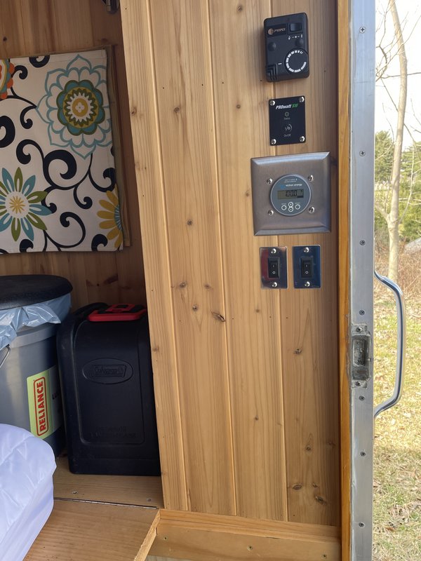
I'm also thinking of getting a small inexpensive touchscreen that works with the Raspberry Pi to simulate the Victron Touch50 or Touch70.

Image

The Victron screens are over $220-320, while a similar sized touchscreen from Waveshare can be had for $50-75. Reading the Victron forums, it seems that Waveshare HDMI/USB touchscreens at 800x480 resolution work out of the box with Venus OS. Kwindrim's Venus software suite (author of GuiMods) also includes an Rpi touchscreen mod that makes installation easy. I am thinking a 4.3" or 5" could go to the left of the battery monitor on the closet wall.

Image
My off-road camper build on an M116A3 military chassis:
http://www.tnttt.com/viewtopic.php?f=50&t=62581
Tow vehicle: 2008 Jeep Liberty with a 4 inch lift.
User avatar
lfhoward
1000 Club
1000 Club
 
Posts: 1370
Joined: Wed Jan 22, 2014 6:10 pm
Location: Philadelphia, PA

Re: M116A3 Build

Postby bdosborn » Mon Feb 27, 2023 1:17 pm

You can use the Pi HDMI out to display the Venus OS on a regular TV. I installed a script to do it awhile back but the script went away with an update. I wasn't horribly impressed with it, I think it was only the remote access screen. I might spring for the Victron Display someday, it would have been nice on our Florida trip, but it's way down on the list of things to do...
Bruec
2009 6.5'X11' TTT - Boxcar
All it takes is a speck of faith and a few kilowatts of sweat and grace.
Image
Boxcar Build
aVANger Build
User avatar
bdosborn
Donating Member
 
Posts: 5494
Images: 772
Joined: Wed May 05, 2004 11:10 pm
Location: CO, Littleton

Re: M116A3 Build

Postby lfhoward » Mon Feb 27, 2023 1:36 pm

bdosborn wrote:You can use the Pi HDMI out to display the Venus OS on a regular TV. I installed a script to do it awhile back but the script went away with an update. I wasn't horribly impressed with it, I think it was only the remote access screen. I might spring for the Victron Display someday, it would have been nice on our Florida trip, but it's way down on the list of things to do...
Bruce

That's interesting. The little screens can be used as monitors too with only HDMI, and the power and touchscreen control are via USB. Thus, I need 2 cables to make it work. I am thinking that I want to install all the cables I might use someday so everything is there, even if I don't spring for a touchscreen this round. The RPiDisplaySetup app by kwindrem should make the software setup easier, and display settings in that app do not disappear with every Venus OS update.
My off-road camper build on an M116A3 military chassis:
http://www.tnttt.com/viewtopic.php?f=50&t=62581
Tow vehicle: 2008 Jeep Liberty with a 4 inch lift.
User avatar
lfhoward
1000 Club
1000 Club
 
Posts: 1370
Joined: Wed Jan 22, 2014 6:10 pm
Location: Philadelphia, PA
Top

Re: M116A3 Build

Postby lfhoward » Wed Mar 01, 2023 10:25 pm

Some goodies I ordered a month ago for the electrical system reboot just showed up!

Image

That inverter is massive. It feels like it is made of solid metal inside when I pick it up. It is definitely beefier than the one it replaces. On the other hand, the wall switch is smaller than I pictured, LOL!

I want to give a shout out to http://www.invertersrus.com for carrying these hard to find items, and for tacking on a free 10 year warranty.

Looking forward to finding some spare time now. :D
My off-road camper build on an M116A3 military chassis:
http://www.tnttt.com/viewtopic.php?f=50&t=62581
Tow vehicle: 2008 Jeep Liberty with a 4 inch lift.
User avatar
lfhoward
1000 Club
1000 Club
 
Posts: 1370
Joined: Wed Jan 22, 2014 6:10 pm
Location: Philadelphia, PA
Top

Re: M116A3 Build

Postby bdosborn » Wed Mar 01, 2023 10:39 pm

Wow, thanks for the link, lots of goodies there. I didn't know that Victron made PWM controllers, I might get one for a portable panel. :thumbsup:
Bruce
2009 6.5'X11' TTT - Boxcar
All it takes is a speck of faith and a few kilowatts of sweat and grace.
Image
Boxcar Build
aVANger Build
User avatar
bdosborn
Donating Member
 
Posts: 5494
Images: 772
Joined: Wed May 05, 2004 11:10 pm
Location: CO, Littleton
Top

Re: M116A3 Build

Postby lfhoward » Sat Mar 04, 2023 11:22 pm

I sketched up some new wiring diagrams for the new (hopefully final) configuration of the M116A3. If you see a problem I don't see, please let me know. But I am mostly posting this so I don't have to keep it all in my head!

Image


Image
My off-road camper build on an M116A3 military chassis:
http://www.tnttt.com/viewtopic.php?f=50&t=62581
Tow vehicle: 2008 Jeep Liberty with a 4 inch lift.
User avatar
lfhoward
1000 Club
1000 Club
 
Posts: 1370
Joined: Wed Jan 22, 2014 6:10 pm
Location: Philadelphia, PA
Top

Re: M116A3 Build

Postby bdosborn » Sun Mar 05, 2023 10:37 am

Here's a couple of things I noticed:

    Your inverter DC wire is bigger than it needs to be, Victron recommends a #4 wire for the 800VA inverter. A #4 marine wire is rated at 125A in open air.

    I don't use mega fuses, there are too many cheap Chinese counterfeits out there. I like MRBF terminal mount, they have a UL listing and they mount right at the battery. Victron says you need a 125A fuse : 125A MRBF Terminal

    I'm not a fan of small ATS, they use a lot of power and they don't sense the voltage phase difference between the inverter and shore power. The inverter output will NOT be in phase with the utility so its a bolted fault when the switch transfers and the two sources are 180 degrees out of phase. If you read the ATS manual fine print you'll see that you shouldn't have shore power connected with the inverter on. Which I did all the time when I had an ATS. Doh! I like rotary manual transfer switches with a center off position. Leave the switch in the center off position for 2 Mississippis when transferring and you don't have to worry about having shore and inverter power on at the same time. And you wont use any battery power when boondocking.

    Fuses on a single PV panel don't do much. There aren't any fuses that coordinate with the fault current of the panel so it's only protection from a catastrophic failure of the PV controller that faults the panel directly to the battery (very unlikely). Since a fuse won't coordinate I'd go with a circuit breaker instead. Then you can easily turn the panels off, which is what I find myself doing way more often that I would have guessed to tinker with things. Midnite Solar is what the pro PV installers use but any DC rated circuit breaker will work.

    I'd put a fuse on the charger output, whatever the manufacturer recommends.

    Victron recommends a circuit breaker on the 120V input and output of the inverter. I used DIN rail mounted breakers as they are small, cheap and easily enclosed. Look for a UL 489 listing as that means its actually been tested as a circuit breaker. I got my breakers for $15 on Amazon but they are $40 now, shop around:
    eBay Linky

    Din Rail Circuit Breaker Box

    Here's a picture of my AC setup; incoming shore power to the inverter is in the left box and inverter output is in the right. The only reason I split the boxes up is to follow the wheel arch. There are tons of DIN rail goodies you can get, I put surge suppression and a voltmeter on my shore power inlet. I've got ground fault protection on the inverter output but you can use a GFCI outlet . The GFCI as you've shown won't protect the inverter output though...

    Image


Hope this helps,
Bruce
2009 6.5'X11' TTT - Boxcar
All it takes is a speck of faith and a few kilowatts of sweat and grace.
Image
Boxcar Build
aVANger Build
User avatar
bdosborn
Donating Member
 
Posts: 5494
Images: 772
Joined: Wed May 05, 2004 11:10 pm
Location: CO, Littleton
Top

Re: M116A3 Build

Postby lfhoward » Sun Mar 05, 2023 12:20 pm

Bruce, thank you for such an in-depth answer, and for the links!

Some quick responses (before more study and deep thinking):
- That battery post fuse is perfect! I will for sure be replacing the mega fuse with that.
- My Progressive Dynamics ATS for RV’s has a 30 second pause built in when changing power sources, so I think that’s how it handles out of phase issues. I want to reverse the directionality of the wiring so that when the inverter is on, the solenoid is at rest and it doesn’t use unnecessary energy. It is rare that I am plugged into shore power anyway, and would not be switching between AC power sources in practice. The ATS just makes it so I don’t have to open the side compartment to turn a switch to be able to plug in or turn on the inverter. Victron makes a slick ATS that handles phase issues and is so instantaneous that electronics even stay on during the changeover when power from one source is lost. https://www.victronenergy.com/upload/documents/Datasheet-and-installation-manual-Filax-2_the-ultra-fast-transfer-switch_EN.pdf But at $343.40 it is pricey!
- The fuses on my diagram that are associated with the two solar charge controllers are actually integrated into the bottom of the Victron units. They are 20A if I remember correctly. It would be nice to have breakers to turn them off though without turning off the whole power system.
- I have an in-line 15A fuse on the solar panel side of the solar charge controllers, as well as a physical switch to cut off solar power. Forgot to include that!

Appreciate your detailed response so much! Thank you.

Edit:
I ordered a 125A battery post fuse, a 16 Amp 2-pole breaker for the 210 watt roof solar panel, and a 2-din enclosure that should fit next to my solar charge controllers. (The 200 watts of auxiliary solar panels can be turned off by just unplugging them from the side of the trailer, and they already have a 15 amp inline fuse.)
My off-road camper build on an M116A3 military chassis:
http://www.tnttt.com/viewtopic.php?f=50&t=62581
Tow vehicle: 2008 Jeep Liberty with a 4 inch lift.
User avatar
lfhoward
1000 Club
1000 Club
 
Posts: 1370
Joined: Wed Jan 22, 2014 6:10 pm
Location: Philadelphia, PA
Top

Re: M116A3 Build

Postby bdosborn » Sun Mar 05, 2023 6:32 pm

lfhoward wrote:- My Progressive Dynamics ATS for RV’s has a 30 second pause built in when changing power sources, so I think that’s how it handles out of phase issues. I want to reverse the directionality of the wiring so that when the inverter is on, the solenoid is at rest and it doesn’t use unnecessary energy. It is rare that I am plugged into shore power anyway, and would not be switching between AC power sources in practice. The ATS just makes it so I don’t have to open the side compartment to turn a switch to be able to plug in or turn on the inverter. Victron makes a slick ATS that handles phase issues and is so instantaneous that electronics even stay on during the changeover when power from one source is lost. https://www.victronenergy.com/upload/documents/Datasheet-and-installation-manual-Filax-2_the-ultra-fast-transfer-switch_EN.pdf But at $343.40 it is pricey!


That delay is perfect, mine went over immediately when it detected the preferred source. I reversed my ATS too so that shore power was the side that energized the relay. I had the trailer plugged in all the time and the ATS relay failed after about a year. To be fair, the manufacturer sent me a replacement logic board and it was easy to fix but that ATS was dead to me by then. :thumbdown:

Yeah, some of Victron's stuff is so pricey that they price themselves right out of the market. I like their batteries but I'll never be able to afford them...

I installed a Mopeka level sensor on my diesel heater fuel tank today. So now I can check the van's water and fuel levels while sitting on the couch:
Image

Bruce
2009 6.5'X11' TTT - Boxcar
All it takes is a speck of faith and a few kilowatts of sweat and grace.
Image
Boxcar Build
aVANger Build
User avatar
bdosborn
Donating Member
 
Posts: 5494
Images: 772
Joined: Wed May 05, 2004 11:10 pm
Location: CO, Littleton
Top

Re: M116A3 Build

Postby lfhoward » Sun Mar 05, 2023 7:47 pm

Nice, Bruce! The Mopeka & Ruuvi sensors have really revolutionized the VRM and made it a lot more informative. I am planning on using the spare timer relay I have to automate the ceiling fan based on indoor temperature, which would be helpful in summer. The VRM relay 2 temperature option can be selected, and you can direct it to a RuuviTag as the data source. I also plan to be able to use VRM relay 3 as a manual override to make the fan circuit energized all the time for manual fan control. In theory we could do something like that with our heaters to maintain a certain interior temperature, but in practice I don’t think we could cut the power that way to our heaters because heat soak would cook their circuit boards. They have to cool down with their fans running for several minutes.
My off-road camper build on an M116A3 military chassis:
http://www.tnttt.com/viewtopic.php?f=50&t=62581
Tow vehicle: 2008 Jeep Liberty with a 4 inch lift.
User avatar
lfhoward
1000 Club
1000 Club
 
Posts: 1370
Joined: Wed Jan 22, 2014 6:10 pm
Location: Philadelphia, PA
Top

Re: M116A3 Build

Postby featherliteCT1 » Sun Mar 05, 2023 8:27 pm

Isn't your shunt actually positioned between the BMS and your negative bus bar rather than as depicted in the drawing?
featherliteCT1
1000 Club
1000 Club
 
Posts: 1125
Joined: Wed Dec 28, 2016 6:54 am
Location: Southern Indiana
Top

Re: M116A3 Build

Postby lfhoward » Sun Mar 05, 2023 9:19 pm

featherliteCT1 wrote:Isn't your shunt actually positioned between the BMS and your negative bus bar rather than as depicted in the drawing?


It's not... but should it be?

(This would be the battery monitor shunt in the drawing, not the smart shunt which is set up just to monitor shore charging.)

I know it would not pick up power usage by the BMS, but I thought the BMS has to be the last thing on the negative line just before the battery. It wouldn't be hard to change it though.
My off-road camper build on an M116A3 military chassis:
http://www.tnttt.com/viewtopic.php?f=50&t=62581
Tow vehicle: 2008 Jeep Liberty with a 4 inch lift.
User avatar
lfhoward
1000 Club
1000 Club
 
Posts: 1370
Joined: Wed Jan 22, 2014 6:10 pm
Location: Philadelphia, PA
Top

Re: M116A3 Build

Postby bdosborn » Sun Mar 05, 2023 11:00 pm

featherliteCT1 wrote:Isn't your shunt actually positioned between the BMS and your negative bus bar rather than as depicted in the drawing?


Good catch, I missed that. The battery monitor shunt should be the first device on the negative side of the battery so that all current goes through it, including the BMS.

Bruce
2009 6.5'X11' TTT - Boxcar
All it takes is a speck of faith and a few kilowatts of sweat and grace.
Image
Boxcar Build
aVANger Build
User avatar
bdosborn
Donating Member
 
Posts: 5494
Images: 772
Joined: Wed May 05, 2004 11:10 pm
Location: CO, Littleton
Top

Re: M116A3 Build

Postby lfhoward » Mon Mar 06, 2023 12:05 am

bdosborn wrote:
featherliteCT1 wrote:Isn't your shunt actually positioned between the BMS and your negative bus bar rather than as depicted in the drawing?


Good catch, I missed that. The battery monitor shunt should be the first device on the negative side of the battery so that all current goes through it, including the BMS.

Bruce

:thumbsup:

Thanks you two!
My off-road camper build on an M116A3 military chassis:
http://www.tnttt.com/viewtopic.php?f=50&t=62581
Tow vehicle: 2008 Jeep Liberty with a 4 inch lift.
User avatar
lfhoward
1000 Club
1000 Club
 
Posts: 1370
Joined: Wed Jan 22, 2014 6:10 pm
Location: Philadelphia, PA
Top

Re: M116A3 Build

Postby featherliteCT1 » Mon Mar 06, 2023 7:23 am

From what I can tell, there are pros and cons associated with mounting the shunt "before" (at the negative battery post) or "after" the BMS.

First below is a link to a brief discussion on diysolarforum. Two of the site moderators give their opinions. The diysolarforum photo reproduced below calls mounting the shunt directly to the negative battery post, like bdosborne suggested, as option #2.

Screenshot 2023-03-06 at 7.12.17 AM.jpg
Screenshot 2023-03-06 at 7.12.17 AM.jpg (164.17 KiB) Viewed 343 times


https://diysolarforum.com/threads/shunt ... bms.23627/

Next below is a link to one of Andy's videos from 2021, with extensive comments about the placement of the shunt. Andy calls mounting the shunt directly to the negative battery post like bdosborne suggested as option #3 (diysolarforum option #2).

Note that Andy says that Victron says to mount the shunt as option #3. Moreover, Andy opted for option #3. I do not know if Andy ever changed his mind.

However, I could not find any Victron statements recommending option #3. All of the wiring diagrams associated with Victron products I have found so far show the shunt connected to a Victron lifepo4 battery with no BMS depicted. My understanding is that the Victron lifepo4 batteries have the BMS inside the case. Consequently, there is no way to connect the shunt as in option #3.

https://www.youtube.com/watch?v=bIyHPAMGOa8

My shunt is currently mounted as diysolarforum option #1; however, I may switch to diysolarforum option #2 (Andy's option #3, as bdosborne suggested) depending upon what you guys recommend.
featherliteCT1
1000 Club
1000 Club
 
Posts: 1125
Joined: Wed Dec 28, 2016 6:54 am
Location: Southern Indiana
Top

PreviousNext

Return to Build Journals

Who is online

Users browsing this forum: No registered users and 48 guests