Another foam standie...

Canvas covered foamies (Thrifty Alternatives...)

Moderator: eaglesdare

Re: Another foam standie...

Postby Wobbly Wheels » Tue Sep 18, 2012 2:06 pm

That's a great way to describe it !

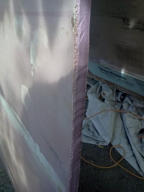
While it's still wet, you can see areas that are resin-rich: they are shinier and...'softer' looking ?... than the rest.
User avatar
Wobbly Wheels
Donating Member
 
Posts: 1080
Joined: Tue Mar 15, 2011 9:51 am

Re: Another foam standie...

Postby Wobbly Wheels » Thu Sep 27, 2012 8:55 pm

Seems like my progress recently hasn't done much more than bump my thread, lol.

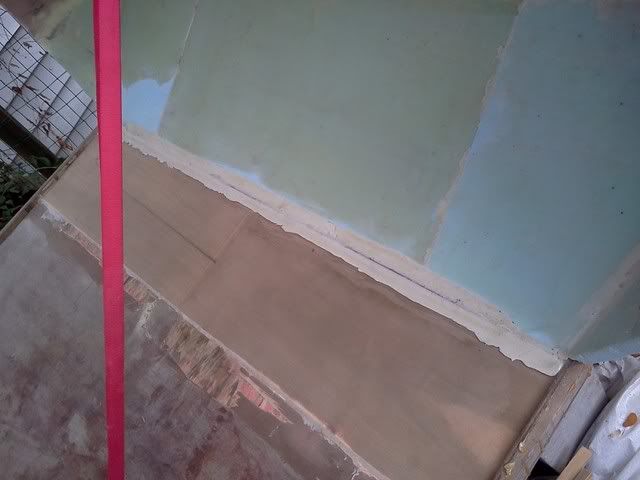
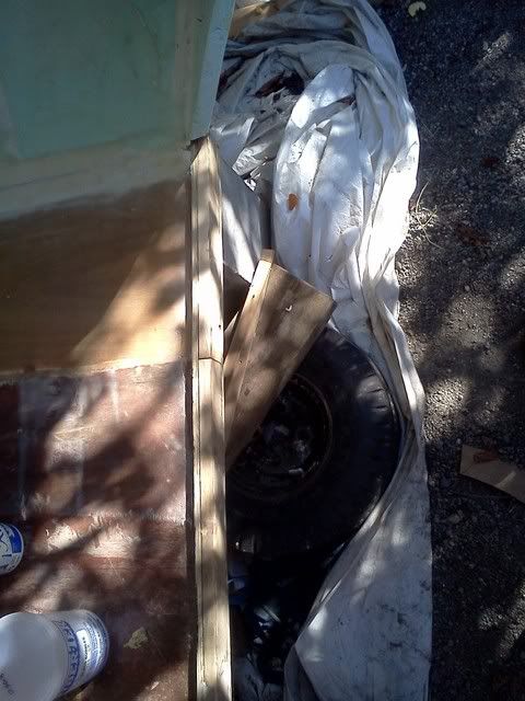
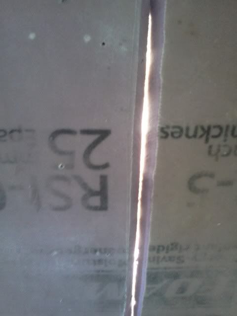
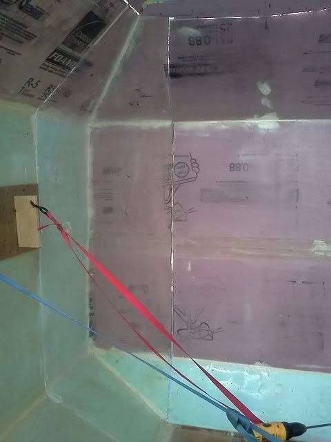
I had planned on glassing the back wall to the floor tonight, but found that some of the GG on the last section of floor had come unstuck. Not much point in a SIP floor if the panels aren't stuck together !
Truth be told, I suspect the failure was on the wood, not the glue - it's cheap@ss 1/8 luan ply: the stuff you use for pattern making and other disposable applications. I've already decided that it's too light to use in a floor sandwich, now it's just a matter of paying for that call.
Once I get cabinetry in, the floor will get another layer of 1/4" (maybe 3/8, but I'm always thinking about weight)
Had I used 1/4 on the top to start with, I think I would have been a happy...camper ?
Lol, live and learn.

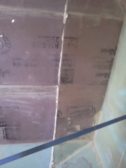
I squirted some canned foam into the voids and weighted it down. I have been surprised at how well canned foam works as an adhesive generally. As long as I control the expansion I am basically using super-foamy GG. The experiences of others seem to bear this out.

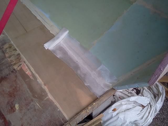
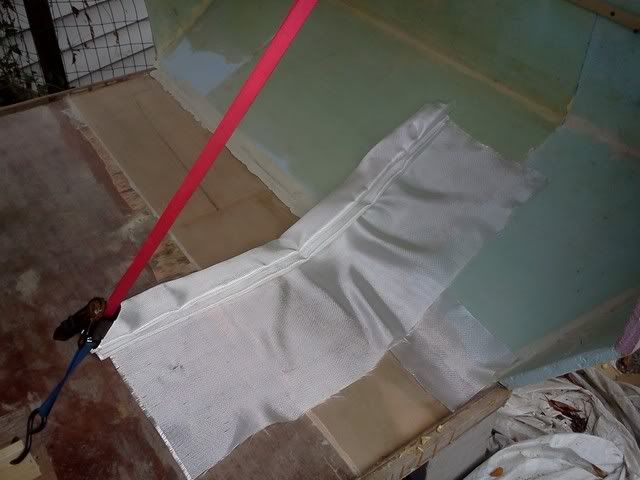
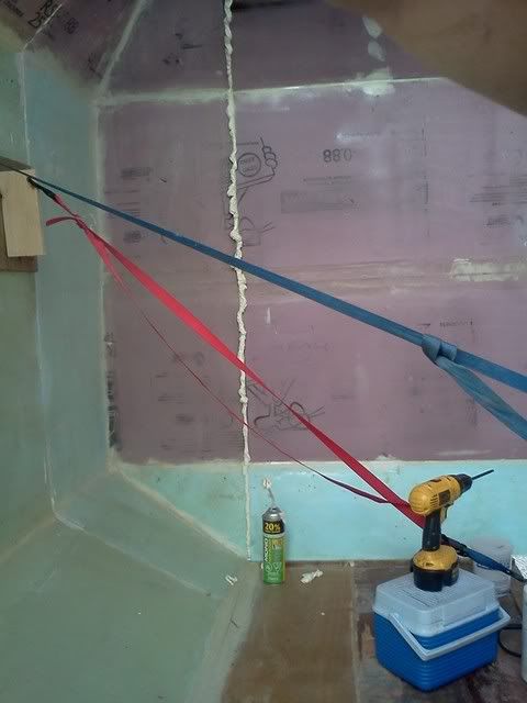
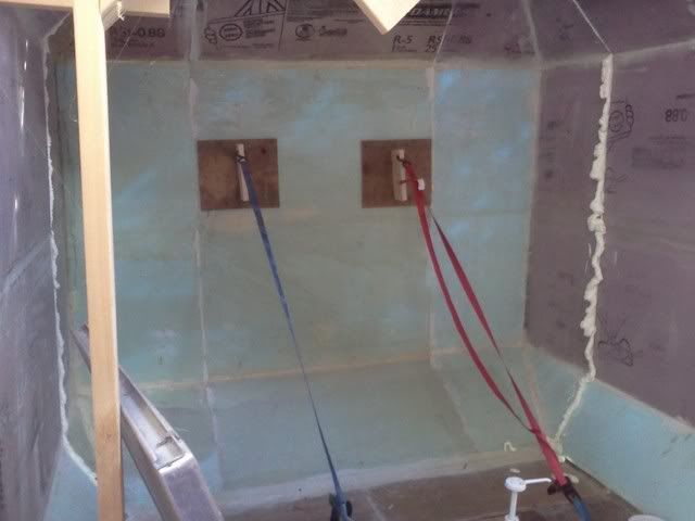
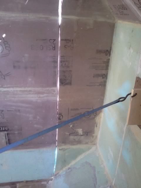
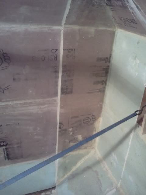
Then I ran a bead of foam along the inside corner where the floor and back wall meet. The process that seems to work best from both a structural standpoint and a Scottish heritage 8) is to build up an inside corner with canned foam and shape it once it hardens. I then skim it with a thin coat of thickened epoxy just before glassing, rather than using the (much more expensive) epoxy for the entire fillet.
The density of the hardened canned foam seems to be the same as the styrofoam, albeit more porous. I don't know that I'd want to use it if it were subjected to much compression....but I'm using cedar blocking for that anyway.

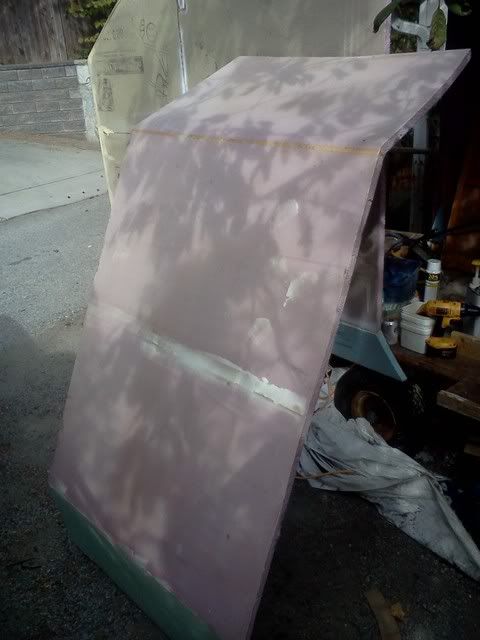
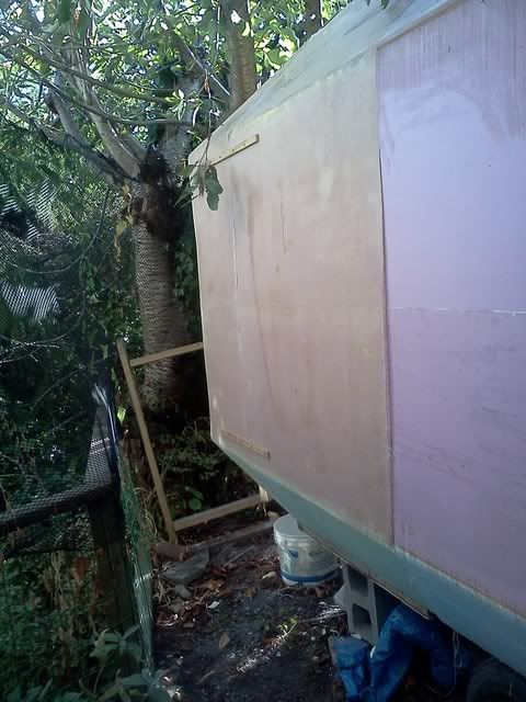
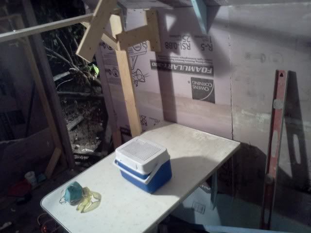
I scrounged a 60W solar rig a while back, but I haven't had much opportunity to play around with it yet. There are pics a few posts back, but since then I've banged up a rack for the panels and stuck 'em on the roof. The four 15W panels (basically the big version of those dashboard battery maintainers) feed into an octopus and that leads runs into the house through a window. The 7.5A charge controller is just inside, as is the battery and a 1000W inverter.
I was planning on powering the bedroom TV from it, since we use that for about four hours every night.
Well, my wife does...I'm snoring by then. The running joke in our house is that I've seen the first half of almost every movie ever made.

I put up the panels where they'll see the most sunlight and wound up at the opposite end of the house (of course).
Name's Murphy you say ? So glad you could make it !
Long story short (longer?), it runs into the kitchen because of cable lengths. didn't want to carry the DC any further than what the manufacturer did and I haven't had time to run a longer extension cord. It comes into the kitchen, so I used it to make my toast this morning. My toaster is 900W and, while it generated a fault tone, it didn't trip the inverter off. It's been charging all day - 19.75 V right now (though that's about to drop off) and 14.35 to the battery. When I unplug the controller, the battery is at 14.25, but that's without waiting for it to equalize either. When the 'charging' light goes out, presumably there's no more forward bias into the battery so I'll check a couple hours after that and see what the battery voltage is.

Image
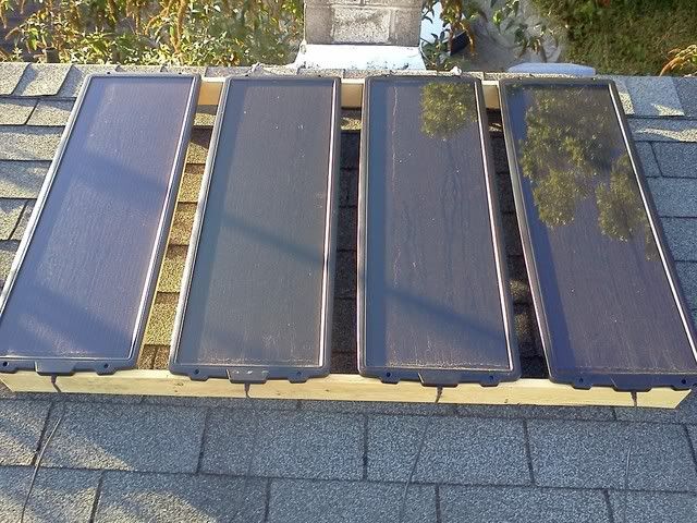
Yeah, I know I gotta hose the dust off 'em...
Image

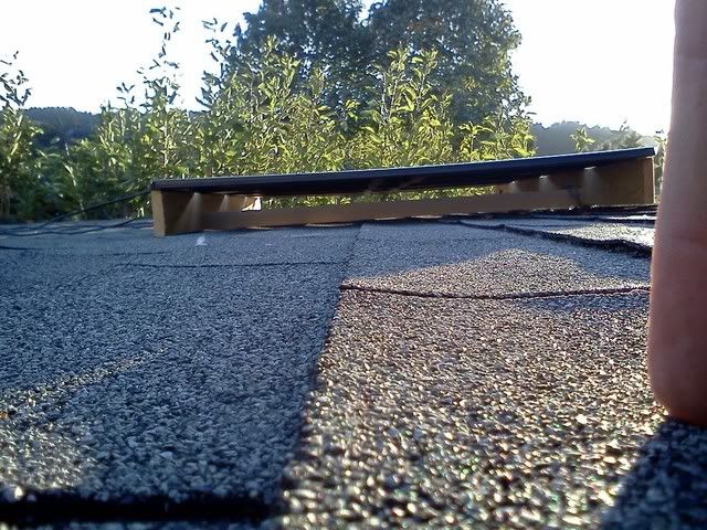
The rack is a mock up of how I'll mount them on the roof of the trailer and I can see already that the plastic frames on these panels don't support their own weight without the center supported so I'll run another rib when I do it in foam. I'll glue a strip of 1" aluminum to the top of the foam ribs before I glass them so that I can drill and tap the mounts rather than screwing them into the glass. That will make it easier to change the configuration later.
User avatar
Wobbly Wheels
Donating Member
 
Posts: 1080
Joined: Tue Mar 15, 2011 9:51 am

Re: Another foam standie...

Postby GPW » Fri Sep 28, 2012 5:17 am

Solar is such a great development eh ... the fuel is Free... the process just needs more research and development , which will come with time ... Not only making electricity , solar can heat water (pasteurize) , Cook , and heat air (heating) ... :thumbsup: 8)
There’s no place like Foam !
User avatar
GPW
Gold Donating Member
 
Posts: 14920
Images: 546
Joined: Thu Feb 09, 2006 7:58 pm
Location: New Orleans
Top

Re: Another foam standie...

Postby Wobbly Wheels » Fri Sep 28, 2012 8:32 am

Yeah, like all things technological - we CAN get there from here...if there's a will to.
It'll take more people embracing it for companies to realize that there's a market for it.
We need to develop panels that are more efficient so they don't take up as much real estate, and technology that allows us to to incorporate solar into everyday surfaces without the need for them to be perpendicular to the sun...an efficient paint or flexible membrane would allow things like roofs, streetlamps and the roofs of cars to be able to generate electrical power.
It doesn't have to provide 100% of usable power right away, just cut down a bit on the power generated from less efficient means.

The WHO publishes a pamphlet about using clear water bottles in the sun to sterilize drinking water (they call it 'SODIS').
Well...they also published 'Tommy', but that's another WHO altogether... :lol:
The water needs to be clear, but the sun is doing the heavy lifting to make the water safe.

One of the guys whose boats I look after kept having to replace batteries. Of all the guys he's had doing that for him in the past, apparently none of them knew that batteries don't like to be left discharged and that you can't just forget about them. After replacing the batteries in all the boats, the quads and the truck (TV for the boats) over the past year due to neglect, everything is now on a maintenance schedule and all of his toys are ready to go whenever he wants to use them.

That's the main reason I wanted to put solar on the trailer - the batteries will always be topped up and ready to go, even though it's not convenient to plug the trailer in where I'm keeping it. Batteries are one place where it's worth it to spend more, and they are too darned expensive to let them waste away.
A $400 solar kit is a cheap way to ensure that they'll last for forever (which means "however long I have the trailer before I build another...")
Getting it for half that is even better :thumbsup:

My battery voltage had equalized to 12.8 when I got up this am: exactly where it should be. I switched the inverter from the toaster to the espresso maker (1000W) and, while the alarm goes on when both the heating element and pump are on, it's more practical as a tester because I use that every morning. After this weekend though it will be running the bedroom TV and satellite receiver instead, which represents the lower draw, longer duration load that deep cycle batteries prefer (it's a TSW inverter, not a square wave)
User avatar
Wobbly Wheels
Donating Member
 
Posts: 1080
Joined: Tue Mar 15, 2011 9:51 am
Top

Re: Another foam standie...

Postby GPW » Fri Sep 28, 2012 8:53 am

Just FYI , I really like Solar cooking ... set it in the Sun , and forget it , till lunchtime ... only slightly slower than regular cooking , no stirring , no burning ... I use it as a Crock Pot , although you can bake in it , but it doesn’t brown meat ...works in winter as long as the sun is out ... naturally ...

Very practical , and Free... if you make your own cookers... I think every camper should have one of these , especially in No Fire areas... :thumbsup: http://solarcooking.wikia.com/wiki/Cate ... oker_plans
There’s no place like Foam !
User avatar
GPW
Gold Donating Member
 
Posts: 14920
Images: 546
Joined: Thu Feb 09, 2006 7:58 pm
Location: New Orleans
Top

Actual, honest-to-goodness progress !

Postby Wobbly Wheels » Sat Sep 29, 2012 6:47 pm

I remember reading about your solar cookers in another thread. I looked it up and I'm stoked to try it. Once I'm camping in the trailer, a solar cooker is on my to do list !

Today was a bit of a milestone, though bigger in significance than in effort expended...
I had already glassed the 3 sections of the back wall together into a single unit and today I glassed them to the floor. The trailer is no longer a flat deck with a pointy-nosed styrofoam box sitting on top of it.

I set up a couple of straps to hold the wall plumb while I glassed it so that I could remove the rear former frame (it was screwed to the floor right where the glass needed to go) . I cut enough 8" tape off the glass roll to go from one side to the other (~62"...so two strips), then I cut a 62" long piece at the full 38" width.
That means that the floor-to-back-wall joint has 8" tape right against the seam, then a huge 38" 'tape' on top of that, and then (thanks to the amount of resin I was able to pull out) I laid in a length of 4" tape on top.

Just before I put the second layer of glass on the outside, I'll wrap a joint from the outside of the wall to the underside of the deck to complete the seam.

And now for some pics to show that it actually happened :)
This is the 'before' pic - note the delam in the cheap@ss ply I used for the floor (lesson learned). I sanded the delaminating layers off and replaced them with a piece of wetted 6oz cloth.
Image

This shows how the first layer of tape will go in
Image

And the second layer that will go on top of that. That generous overlap shows why the glassing on the edges of the pieces isn't critical. There will also be an additional layer in the corners when the sidewalls are glassed in the same way...on top of the buildup already in the corner from the way the initial layer of cloth was cut during the layup of the corner piece down on the bench. Essentially, the two back corners are very well reinforced vertical posts.
Image

Wetted out, with the extra layer of 4" tape on top.
Image
User avatar
Wobbly Wheels
Donating Member
 
Posts: 1080
Joined: Tue Mar 15, 2011 9:51 am
Top

Re: Another foam standie...

Postby GPW » Sun Sep 30, 2012 8:49 am

Wow!!! , Cool !!! Starting to take on that space craft “shuttle “ look ... 8) :thumbsup: Just Gotta’ be strong with all that “reinforcement “ ... :thinking:
There’s no place like Foam !
User avatar
GPW
Gold Donating Member
 
Posts: 14920
Images: 546
Joined: Thu Feb 09, 2006 7:58 pm
Location: New Orleans
Top

Re: Another foam standie...

Postby Wobbly Wheels » Sun Sep 30, 2012 11:55 am

"shuttle look"...hmmm...you've given me an idea for a paint scheme... :thinking:
Haven't posted too many pictures of the whole shape, but it DOES kinda look 'shuttle-y'.
Or maybe space junk... depends on the day.
:lol:
User avatar
Wobbly Wheels
Donating Member
 
Posts: 1080
Joined: Tue Mar 15, 2011 9:51 am
Top

Re: Another foam standie...

Postby Wobbly Wheels » Sun Sep 30, 2012 7:20 pm

Rocketing forward at an astronomical pace...I got both of the sidewall bevels formed and got the next panels glued in.
I beveled the mating edges on the inside of the joint to make room for glue. I didn't touch the outside edge because that's the important surface to align with the adjacent panel (that's the one you'll see).
Here's the wall panel before

Image

And here's the bevel. One of the things about this method is that, because of the expansion of the canned foam, the amount or depth of bevel isn't critical: the foam will expand to fill it. This went REALLY quick with a 60G disc in an angle grinder !
Image
I didn't take a pic, but on the bottom I left a 'leg' at each end and sanded out a generous bevel between them. When I glue in the bottom I'll try and remember to show that.

Then I prepped the floor frame to receive the wall section: a quick sand of the old overexpanded GG runs (more is always better, right ?).
Image
I'd have to go back and check, but I think I built the frame before I decided to cant the walls outward. You can see the 3/4" stock furred with a strip of 1/4" ply to make up the 1" foam thickness of a wall sitting vertically on top of it. To get 100% contact with a 45degree wall, that would need to be 1 1/2" (actually 1.414")....not that it matters at this point. A bit of time with a sanding block solves most problems...well, that and the generous use of high explosives.

This is the left (street) side offered up after beveling. On the outside are the strips of 1/4" ply I've been using to tack sections in place with drywall screws. That keeps the outside of the seam nice and flush and hold the parts against the expansion of the foam. The bevel is uneven but...who are we kidding...that's an angle grinder for you: quick but certainly not a finishing tool (much like the aforementioned explosives)
[img]http://i1202.photobucket.com/albums/bb363/Folder1966/IMG641.jpg?t=1349048986[img]

This is the joint after foaming:
Image
A bevel cut in the end of the applicator and the careful moderation of the trigger allows you to get foam all the way through the joint without voids that would have to be filled before glassing.

This is the left (curb) side after beveling and offered up into place, secured with a couple of the ply straps.
The wall forward of there is unglassed as yet, so it's not as rigid and able to flex inward. It really shows how much rigidity the glass adds. The glassed (aft) seam is perfectly flush - I know that it has to go in because that's where it came out of, but there's something satisfying when you offer up a piece and it fits like a glove...
Image

And a shot of the same seam from the inside. I beveled both edges on this one: that's how I'll do the rest of them.
[/img]http://i1202.photobucket.com/albums/bb363/Folder1966/IMG644.jpg?t=1349048953[/img]

A closeup of the bevel:
Image

And right after I goobered it up:
Image

After taking out the rear former, I rigged up a couple straps to hold the back wall plumb. The bottom is fixed, so it acts as a bit of a hinge. Those plates you see have 16 screws each because it was important to have a lot of small pulls over a large area (12"X12") rather than just a few, which would easily pull out of the laminate. This allows me to keep the back face plumb and take out any twist.
Image

And, because I haven't posted one in a while, here's an overall shot...looks the same as it did last winter !
Not inside though...and there's glass that you can't really make out...
Image
Glen's 'shuttle' comment has been with me all day....light paint and dark windows were already in the plan (thermal)... :thinking:

I've also been thinking about tongue jacks. I have left myself space to attach one of these to the forward wall with the leg dropping down through the bridle.
Image
Instead, I think I might cut off the coupler altogether and have a tongue extension made up. This coupler is welded on, but I can grind it off and have a local shop make a sleeve to go over it that will allow me to bolt a coupler onto a longer piece of tube. It's not so much for the sake of the jack, but for the fact that I can't really do what I want to with the LPG bottle(s) because there just isn't room: one of the compromises I had to make. The trailer is already small enough for our needs but I can't possibly sacrifice any interior space, and I want room to make up a fairing for the bottle(s) both for fuel economy and (more importantly) to keep them out of the weather and secure since I may be leaving the trailer in the bush somewhere as a hunting camp.
User avatar
Wobbly Wheels
Donating Member
 
Posts: 1080
Joined: Tue Mar 15, 2011 9:51 am
Top

Re: Another foam standie...

Postby Wobbly Wheels » Sun Sep 30, 2012 7:27 pm

Rocketing forward at an astronomical pace...I got both of the sidewall bevels formed and got the next panels glued in.
I beveled the mating edges on the inside of the joint to make room for glue. I didn't touch the outside edge because that's the important surface to align with the adjacent panel (that's the one you'll see).
Here's the wall panel before

Image

And here's the bevel. One of the things about this method is that, because of the expansion of the canned foam, the amount or depth of bevel isn't critical: the foam will expand to fill it. This went REALLY quick with a 60G disc in an angle grinder !
Image
I didn't take a pic, but on the bottom I left a 'leg' at each end and sanded out a generous bevel between them. When I glue in the bottom I'll try and remember to show that.

Then I prepped the floor frame to receive the wall section: a quick sand of the old overexpanded GG runs (more is always better, right ?).
Image
I'd have to go back and check, but I think I built the frame before I decided to cant the walls outward. You can see the 3/4" stock furred with a strip of 1/4" ply to make up the 1" foam thickness of a wall sitting vertically on top of it. To get 100% contact with a 45degree wall, that would need to be 1 1/2" (actually 1.414")....not that it matters at this point. A bit of time with a sanding block solves most problems...well, that and the generous use of high explosives.

This is the left (street) side offered up after beveling. On the outside are the strips of 1/4" ply I've been using to tack sections in place with drywall screws. That keeps the outside of the seam nice and flush and hold the parts against the expansion of the foam. The bevel is uneven but...who are we kidding...that's an angle grinder for you: quick but certainly not a finishing tool (much like the aforementioned explosives)
Image

This is the joint after foaming:
Image
A bevel cut in the end of the applicator and the careful moderation of the trigger allows you to get foam all the way through the joint without voids that would have to be filled before glassing.

This is the right (curb) side after beveling and offered up into place, secured with a couple of the ply straps.
The wall forward of there is unglassed as yet, so it's not as rigid and able to flex inward, which you can see on the outside. It really shows how much rigidity the glass adds. The glassed (aft) seam is perfectly flush - I know that it has to go in because that's where it came out of, but there's something satisfying when you offer up a piece and it fits like a glove...
Image

And a shot of the same seam from the inside. I beveled both edges on this one: that's how I'll do the rest of them.
Image

A closeup of the bevel:
Image

And right after I goobered it up:
Image

After taking out the rear former, I rigged up a couple straps to hold the back wall plumb. The bottom is fixed, so it acts as a bit of a hinge. Those plates you see have 16 screws each because it was important to have a lot of small pulls over a large area (12"X12") rather than just a few, which would easily pull out of the laminate. This allows me to keep the back face plumb and take out any twist.
Image

And, because I haven't posted one in a while, here's an overall shot...looks the same as it did last winter !
Not inside though...and there's glass that you can't really make out...
Image
Glen's 'shuttle' comment has been with me all day....light paint and dark windows were already in the plan (thermal)... :thinking:

I've also been thinking about tongue jacks. I have left myself space to attach one of these to the forward wall with the leg dropping down through the bridle.
Image
Instead, I think I might cut off the coupler altogether and have a tongue extension made up. This coupler is welded on, but I can grind it off and have a local shop make a sleeve to go over it that will allow me to bolt a coupler onto a longer piece of tube. It's not so much for the sake of the jack, but for the fact that I can't really do what I want to with the LPG bottle(s) because there just isn't room: one of the compromises I had to make. The trailer is already small enough for our needs but I can't possibly sacrifice any interior space, and I want room to make up a fairing for the bottle(s) both for fuel economy and (more importantly) to keep them out of the weather and secure since I may be leaving the trailer in the bush somewhere as a hunting camp.
Last edited by Wobbly Wheels on Mon Oct 01, 2012 8:30 pm, edited 1 time in total.
User avatar
Wobbly Wheels
Donating Member
 
Posts: 1080
Joined: Tue Mar 15, 2011 9:51 am
Top

Re: Another foam standie...

Postby KCStudly » Sun Sep 30, 2012 8:19 pm

Image
Image

You've got some momentum now! Keep it rolling, you almost have the whole shell done! :thumbsup:
KC
My Build: The Poet Creek Express Hybrid Foamie

Poet Creek Or Bust
Engineering the TLAR way - "That Looks About Right"
TnTTT ORIGINAL 200A LANTERN CLUB = "The 200A Gang"
Green Lantern Corpsmen
User avatar
KCStudly
Donating Member
 
Posts: 9640
Images: 8169
Joined: Mon Feb 06, 2012 10:18 pm
Location: Southeastern CT, USA
Top

Re: Another foam standie...

Postby Wobbly Wheels » Sun Sep 30, 2012 10:58 pm

Thx KC: pretty happy to be back on the job: I just cracked a fresh gallon of resin so look out !!!
At this point, it's becoming more about money than time because I'm into a 'glassing' rather than a 'design' phase. Still, it feels pretty good to be able to get something done on the trailer this weekend. I have a fresh gallon of resin so progress is inevitable....probably...

I went back and trimmed out the seams so I can glass them this week:
Image

Here's my rough dinette location.
Image

The table is 24" wide but I have no problems cutting it down. The left edge of the level is the edge of the bunk. Given that the table needs to serve only two, I figure 12" ought to be lots of table depth. As it is, I have 42" for dinette width, which seems to be an RV standard..but I'm wide open to opinion on that !
Thoughts ? Opinions ?
Derision, even...?

This is the pattern of the early 70's tabletop laminate, so I definitely want to preserve it if I can. Fortunately the underside of the table was sealed, making my job much easier.
Image
User avatar
Wobbly Wheels
Donating Member
 
Posts: 1080
Joined: Tue Mar 15, 2011 9:51 am
Top

Re: Another foam standie...

Postby GPW » Mon Oct 01, 2012 4:59 am

W2, really moving right along !!! Looking GOOD !!! :thumbsup: 8) ;)
There’s no place like Foam !
User avatar
GPW
Gold Donating Member
 
Posts: 14920
Images: 546
Joined: Thu Feb 09, 2006 7:58 pm
Location: New Orleans
Top

Re: Another foam standie...

Postby KCStudly » Mon Oct 01, 2012 2:47 pm

Leave the table as big as you think you can get away with. If it ends up too big and annoys you, you can always cut it down. If it ends up too small and you find yourself wishing you had left it bigger, oh well. :roll:

Try it out big, then decide.
KC
My Build: The Poet Creek Express Hybrid Foamie

Poet Creek Or Bust
Engineering the TLAR way - "That Looks About Right"
TnTTT ORIGINAL 200A LANTERN CLUB = "The 200A Gang"
Green Lantern Corpsmen
User avatar
KCStudly
Donating Member
 
Posts: 9640
Images: 8169
Joined: Mon Feb 06, 2012 10:18 pm
Location: Southeastern CT, USA
Top

Re: Another foam standie...

Postby Wobbly Wheels » Mon Oct 01, 2012 8:20 pm

True enough KC.
It's the old carpenter's adage: you can always take a little more off but it's tough to put it back.
I'm probably going to use something like this on the other side, so I have some flexibility there anyway.
Image

Not that it's a call I have to make now, anyway...
User avatar
Wobbly Wheels
Donating Member
 
Posts: 1080
Joined: Tue Mar 15, 2011 9:51 am
Top

PreviousNext

Return to Foamies

Who is online

Users browsing this forum: No registered users and 8 guests