Can't wait to see what the super-secret project is. Whatever you're doing, I'll bet it comes out looking great given the attention going into it.
You probably know this already but, if you're going with a GFI inside the cabinet, they don't fit too well in those shallow boxes.
The Poet Creek Express - Foamie Hybrid
Moderator: eaglesdare

Re: The Poet Creek Express - Foamie Hybrid
![]() by KCStudly » Sun Feb 01, 2015 11:54 pm
by KCStudly » Sun Feb 01, 2015 11:54 pm
Thanks for the vote of confidence WW. It is just a small project, but I think it will play better and make more sense if I present it all as one entry. Not really that big of a deal, but I think people will like the novelty of it. Hint: it will be useful for DO cooking.
All circuit protection will be in the TB at the source. I figure if I need more depth in the box later for 110v I can add an extension and trim it with maple like the rest. For now I just want to get the wires in there for future reference. More likely it will be used as a 12v drop.
Here was the first location I thought of for the ceiling outlet. This is looking from the curb side with the vent fan opening on the right for reference. I liked this location because I figured I could run the wires with the fan wires, use the void under the fan trim to make the turn rearwards (making it conceivable to service the wires in future despite the turn), only have to drill one hole in the rear fan spar, and have the stiffening flange around the outlet serve as a router template with plenty of room in between the spars for the router shoe.
Then I realized that the knock outs, or rather, the wire entrance strain clips are on the ends of the box. That meant that if I ever had to pull these or more wires, they would have to turn to get in the box. Not the end of the world because the box will be removable, but not ideal. I considered turning the box lengthwise, but then the router shoe would hit the rear spar, and the front edge of the outlet cover would be closer to the front of the cabinet than I wanted. So I decided to move it back behind the rear spar.
Next I tried to fish the wires down thru the passage at the top of the curb side wall, but the hole thru the top of the dome light blocking just wasn’t big enough to accept the extra wires, and I didn’t want to pull the other wires out only to drill the hole bigger and find that I still couldn’t get them down thru the wall.
Plan B, route the wires thru the front wall toe kick and up over the roof drilling thru all of the spars, just like on a traditional build. We’re committed now.
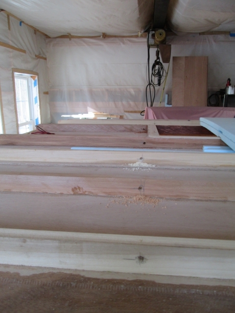
The wires will come from the TB thru the Sealtite conduit that passes thru the bottom of the locker; into the wire way along the lower front wall toe kick; travel a few inches toward the curb side to clear the locker; punch into the toe kick to an intersecting hole drilled down into the toe kick from the outside. The available location for that hole was determined by the locker (on the right), the lower axe handle mount blocking (on the left) and one of the deck screws securing the toe kick to the floor (recess filled with sawdust in the following pic). Kind of tight.
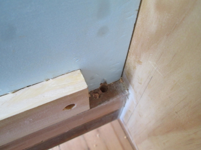
Not shown, by carefully measuring relative to the outside and referencing the locker inside/outside, I was able to drill from the inside near floor level into the front wall/toe kick to intersect this hole.
Following the wire path up, the hole thru the rock guard blocking just missed the pocket screw holding that to the locker.
As the wires move up along the front radius they will cut diagonally to a line just to the outside from the curb side roof vent side brace. I figure I am very unlikely to try to attach anything to the front radius later, especially since there won’t be any blocking there anyway, so not a bad place to let the wiring run as needed. Here is the line of holes in the spars looking from the front rearward.
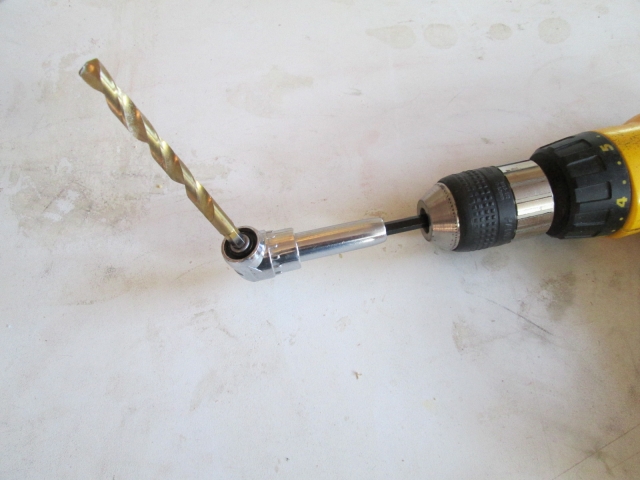
Karl had this angle drive attachment with hex shanked drill bits that made it possible to drill thru the more closely spaced spars at a perpendicular angle.
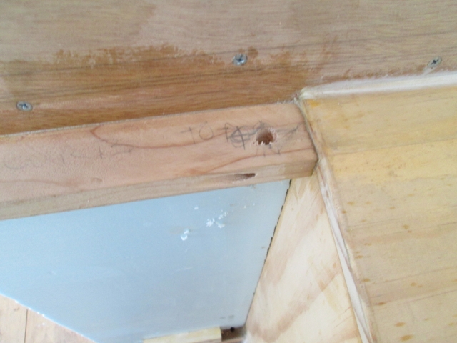
Standing in the galley looking forward, the wire path makes one more jog inboard between the rear fan spar and the last spar in front of the hinge spar.
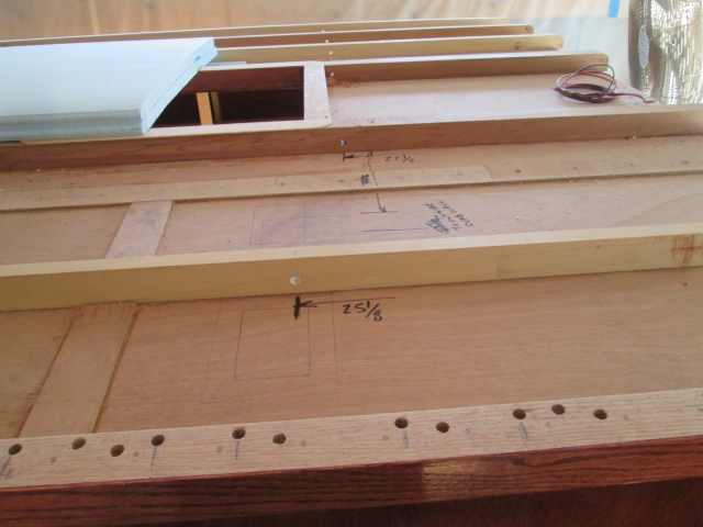
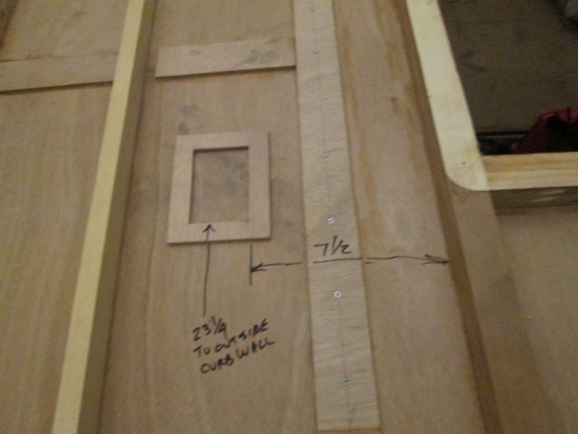
Here are a couple of pics documenting the distance from the outside face of the curb side wall and the centerlines of the wire path. First pic is the rear spar with the outlet flange location traced on the ceiling up against the back of the spar.
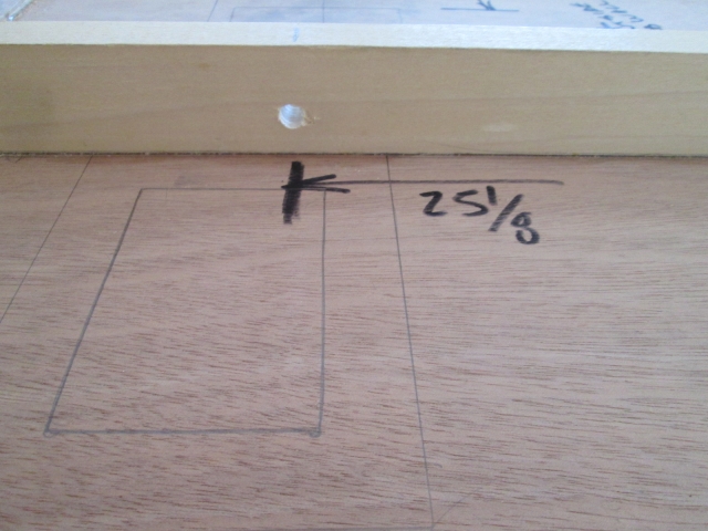
Next is the rear fan spar.
I used the utility knife to rough cut the outlet hole. Once I had scored thru a few layers it was easier to carve away some of the waste in a wedge shape, freeing up the knife blade to make a few more scores.
I tried to be careful not to press too hard scoring so as not to splinter out the finished inside surface, but still managed to get a fairly sizeable chip out (sorry, blurry pic).
Little dab of glue and a clamp should take care of that.
Next up was to glue the stiffening flange to the opening.
I should be able to get the trim router around most of three sides, then I’ll deal with the last of it by sanding or rasping as needed.
Spent some time dusting off the roof in prep for fitting the foam, but stopped short of firing up any power tools.
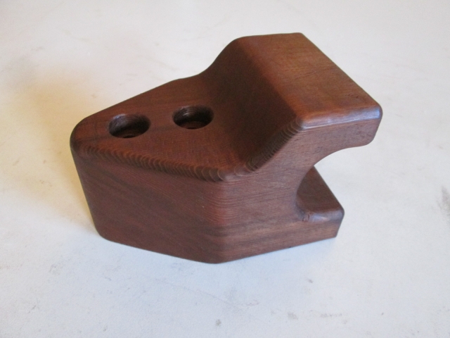
As a reward for making decent progress, I allowed myself to rub some stain onto the shovel handle mount.
All circuit protection will be in the TB at the source. I figure if I need more depth in the box later for 110v I can add an extension and trim it with maple like the rest. For now I just want to get the wires in there for future reference. More likely it will be used as a 12v drop.
Here was the first location I thought of for the ceiling outlet. This is looking from the curb side with the vent fan opening on the right for reference. I liked this location because I figured I could run the wires with the fan wires, use the void under the fan trim to make the turn rearwards (making it conceivable to service the wires in future despite the turn), only have to drill one hole in the rear fan spar, and have the stiffening flange around the outlet serve as a router template with plenty of room in between the spars for the router shoe.
Then I realized that the knock outs, or rather, the wire entrance strain clips are on the ends of the box. That meant that if I ever had to pull these or more wires, they would have to turn to get in the box. Not the end of the world because the box will be removable, but not ideal. I considered turning the box lengthwise, but then the router shoe would hit the rear spar, and the front edge of the outlet cover would be closer to the front of the cabinet than I wanted. So I decided to move it back behind the rear spar.
Next I tried to fish the wires down thru the passage at the top of the curb side wall, but the hole thru the top of the dome light blocking just wasn’t big enough to accept the extra wires, and I didn’t want to pull the other wires out only to drill the hole bigger and find that I still couldn’t get them down thru the wall.
Plan B, route the wires thru the front wall toe kick and up over the roof drilling thru all of the spars, just like on a traditional build. We’re committed now.
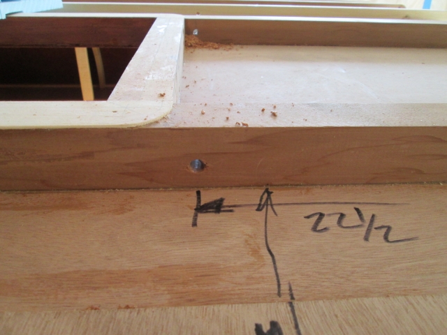
The wires will come from the TB thru the Sealtite conduit that passes thru the bottom of the locker; into the wire way along the lower front wall toe kick; travel a few inches toward the curb side to clear the locker; punch into the toe kick to an intersecting hole drilled down into the toe kick from the outside. The available location for that hole was determined by the locker (on the right), the lower axe handle mount blocking (on the left) and one of the deck screws securing the toe kick to the floor (recess filled with sawdust in the following pic). Kind of tight.
Not shown, by carefully measuring relative to the outside and referencing the locker inside/outside, I was able to drill from the inside near floor level into the front wall/toe kick to intersect this hole.
Following the wire path up, the hole thru the rock guard blocking just missed the pocket screw holding that to the locker.
As the wires move up along the front radius they will cut diagonally to a line just to the outside from the curb side roof vent side brace. I figure I am very unlikely to try to attach anything to the front radius later, especially since there won’t be any blocking there anyway, so not a bad place to let the wiring run as needed. Here is the line of holes in the spars looking from the front rearward.
Karl had this angle drive attachment with hex shanked drill bits that made it possible to drill thru the more closely spaced spars at a perpendicular angle.
Standing in the galley looking forward, the wire path makes one more jog inboard between the rear fan spar and the last spar in front of the hinge spar.
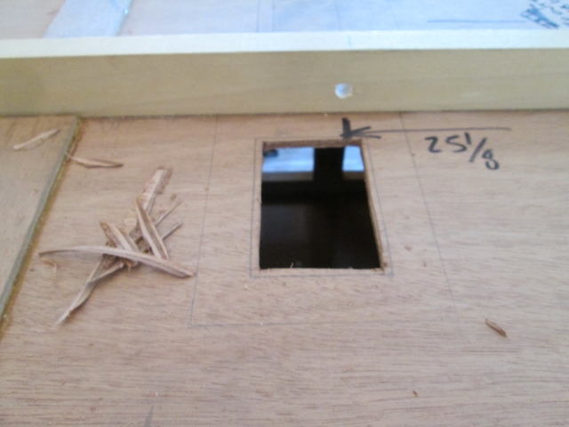
Here are a couple of pics documenting the distance from the outside face of the curb side wall and the centerlines of the wire path. First pic is the rear spar with the outlet flange location traced on the ceiling up against the back of the spar.
Next is the rear fan spar.
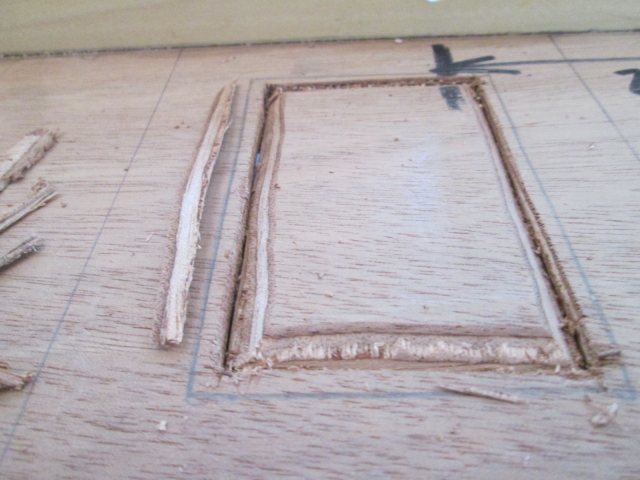
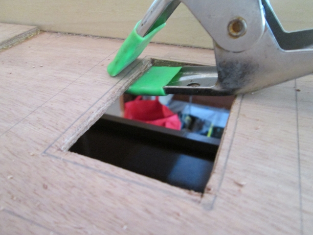
I used the utility knife to rough cut the outlet hole. Once I had scored thru a few layers it was easier to carve away some of the waste in a wedge shape, freeing up the knife blade to make a few more scores.
I tried to be careful not to press too hard scoring so as not to splinter out the finished inside surface, but still managed to get a fairly sizeable chip out (sorry, blurry pic).
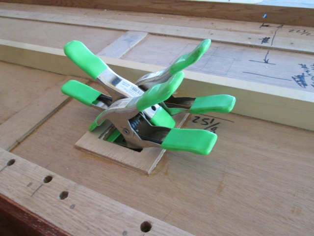
Little dab of glue and a clamp should take care of that.
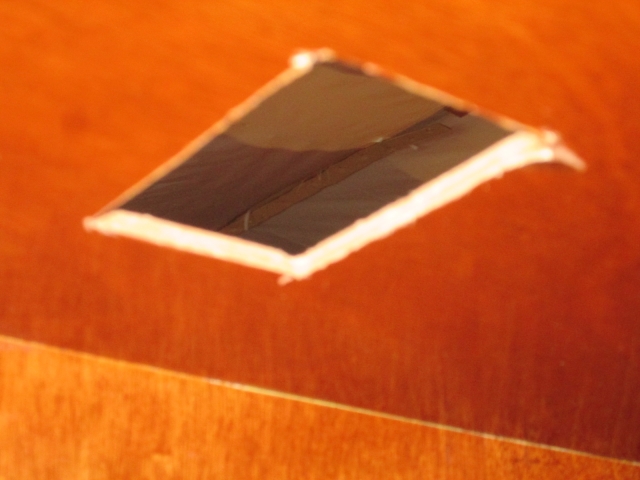
Next up was to glue the stiffening flange to the opening.
I should be able to get the trim router around most of three sides, then I’ll deal with the last of it by sanding or rasping as needed.
Spent some time dusting off the roof in prep for fitting the foam, but stopped short of firing up any power tools.
As a reward for making decent progress, I allowed myself to rub some stain onto the shovel handle mount.
KC
My Build: The Poet Creek Express Hybrid Foamie
Poet Creek Or Bust
Engineering the TLAR way - "That Looks About Right"
TnTTT ORIGINAL 200A LANTERN CLUB = "The 200A Gang"
Green Lantern Corpsmen
My Build: The Poet Creek Express Hybrid Foamie
Poet Creek Or Bust
Engineering the TLAR way - "That Looks About Right"
TnTTT ORIGINAL 200A LANTERN CLUB = "The 200A Gang"
Green Lantern Corpsmen
-

KCStudly - Donating Member
- Posts: 9640
- Images: 8169
- Joined: Mon Feb 06, 2012 10:18 pm
- Location: Southeastern CT, USA