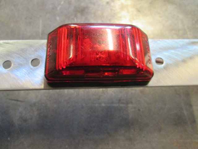
Recapping a bit, at first I thought I would just add a 3-light bar (needed for vehicles greater than 80 inches wide) somewhere at the back, probably down on the trailer frame. So I bought an LED 3-light bar assembly. After further consideration and review of the NHTSA requirements I decided to do it up properly, placing the 3 lights high up on the hatch with two additional rearward facing lights to the outsides. I decided that rather than having one large “eyebrow” in the middle (a faired bump with vertical rear face so that the lights would aim rearward rather than just sit on the surface of the hatch facing mostly up), and two more to the sides of the hatch, I would much prefer five individual eyebrows (or nacelles). Not wanting to extend my budget out that much further, having already spent money on the 3-light fixture, I decided to deconstruct it by removing the OEM stainless steel mounting strip and finding a way to surface mount the individual light/lens assemblies.
The thin SS mounting plate for the original assembly was draw stamped with a shallow recessed cavity in the back for the wires to run between the lights and for the screw heads that held them from the back. From there I designed “simple” flat stainless steel individual mounting plates. These will cover over the small wire recesses that I have routed where these lights will go, allowing the fixture screw heads and wires to bump out the back; and will extend to the right and left of each light forming tabs for the screws that will mount them to the camper.
Once that was all decided, if I am recalling the sequence of events correctly, I decided to go ahead and add the front and rear high clearance lights to the sides of the camper, as well. The same light is available in both red and amber in a single post mount style w/ SS trim (amber for the front side lights red for the rear sides); the mounting trim is also removable on these. The cost of the 3-light bar is about the same as two of the single mount style, so I can get a spare red included by going that way.
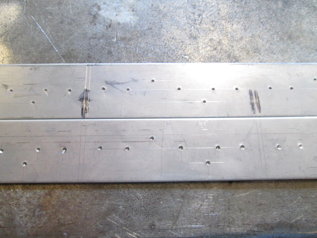
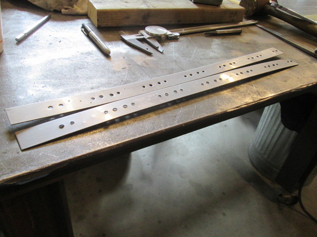
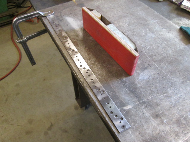
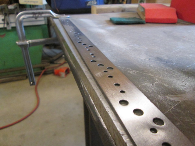
Anyway, like I said, Karl had sheared some strips of .050 thk 304SS for me to make the new mounting plates. Here is my sketch and the strips after I started laying the pattern out.
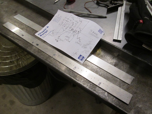
I’ll lay out all nine (9) of the required plates, plus whatever will fit on the stock “incase-ya” screw up, with allowance for saw cutting them into individual pieces after punching the holes and deburring.
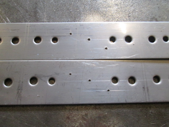
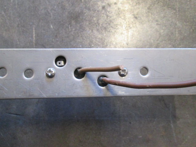
Each plate gets seven (7) holes punched: (2) at 5/32 inch for the screws that hold the light to the plate; (2) at 3/16 for the screws that hold the assembly to the camper; and (3) at 1/4 inch as clearance holes for the wires, one POS, one NEG, and one to isolate the jumper wire from shorting out where the originals were daisy chained (I’ll snip these extra wires off close and pot them with some silicone or liquid electrical tape, but I wanted to be sure they won’t have a chance to touch the mount).
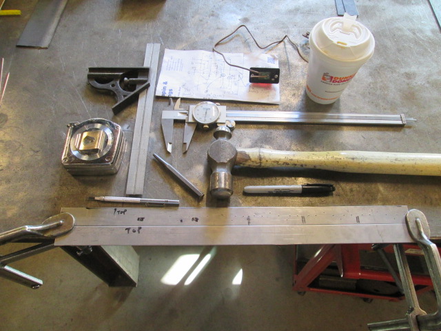
Here are the tools I used. A couple of clamps to hold the strips to the edge of the bench; a layout square (note how the edge of the strip is hanging off the bench a little so that the bench doesn’t interfere with the square); a carbide tipped scribe; measuring tape; prick punch; ball peen hammer; dial caliper; and sharpie marker. Not shown is a leather dead blow hammer and block of wood that will come into play soon.
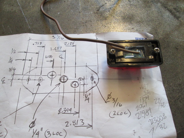
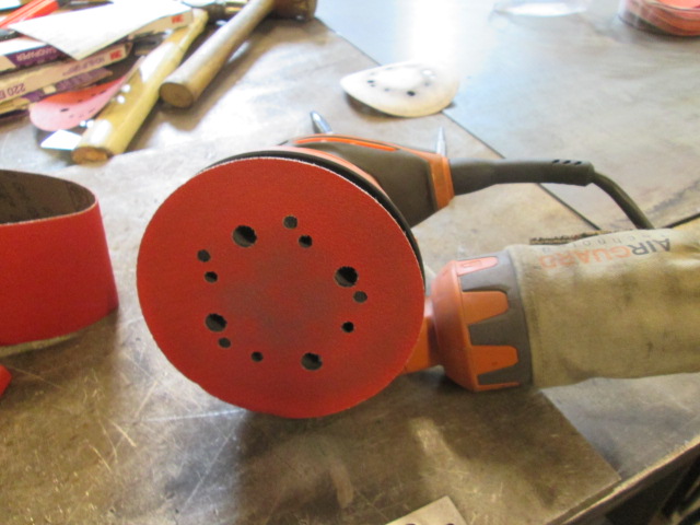
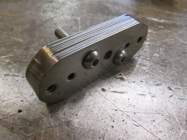
Here’s another look at the sketch and back of the light.
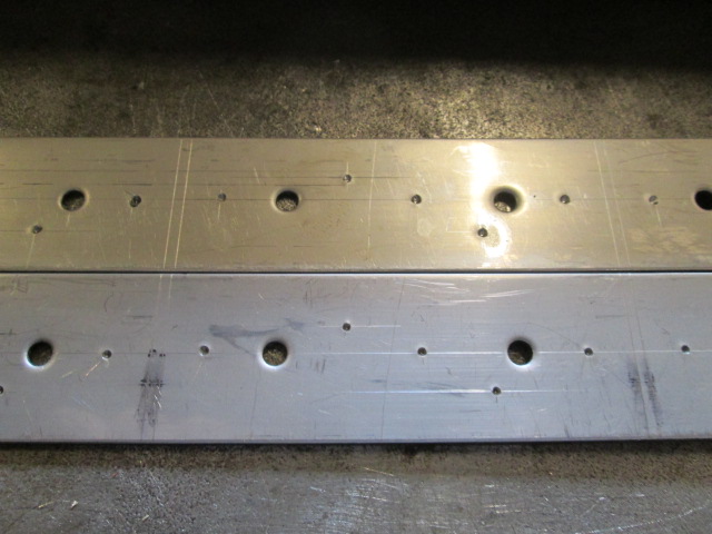
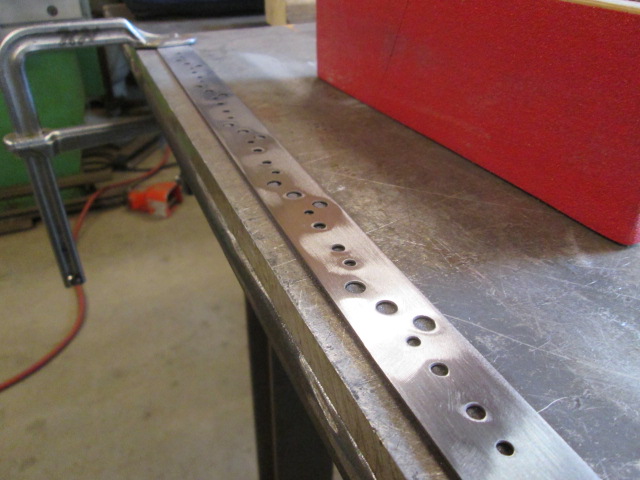
It’s a bit “Primitive Pete”, but you can use the dial calipers as a marking tool to scratch reference lines along the stock. Here you can see the saw cut reference lines and the prick punch marks that will be used to locate the guide points on the hole punches.
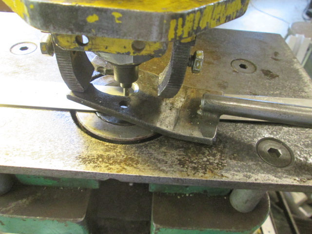
Recall that the front end of Karl’s hydraulically operated iron worker has a hole punch feature, and he has a large selection of different sized punch and die sets.
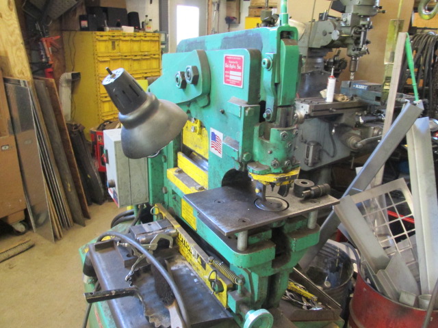
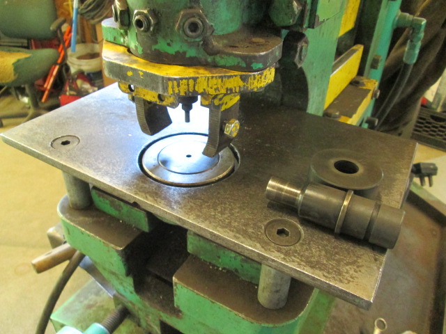
Each punch has a little pointy tit on its tip (just like a transfer punch) that registers into the prick punch marks. By releasing the arbor latch you manually lower the punch to align the tip in your mark, and then when you step on the pedal the press catches up and punches the hole.
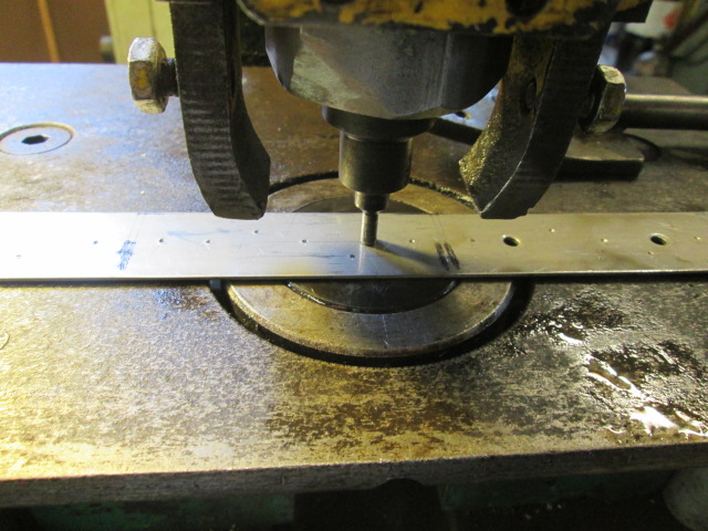
The punch will want to drag on the part on the way out. Normally the yellow stripper ears adjacent to the punch would hold the part back and allow the punch to retract, but when working near the edge of a part, or with thin material like this, you need the stripper to support closer to the hole; so this little hand held forked stripper tool is inserted around the punch to support the material around the hole and prevent the whole thing from getting mangled (I would normally hold the tool flat, but I needed a free hand to take the picture… use your imagination).
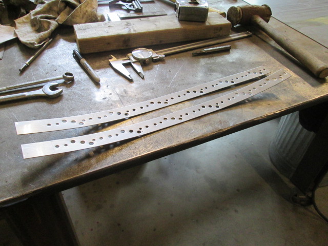
I punched the smallest size holes first then progressed to the larger holes based on the rationale that the part would curl from the deformation and the smaller punches would deform less.
Second set of holes.
You can see the raised burrs on the back (actually, what would become the fronts), and you can start to see the amount of curl being introduced (although I did do some straightening along the way).
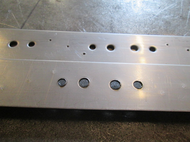
Last set of holes, lots of curl, back piece partially straightened, both by hand and using the leather mallet over the wood 2x4.
Once I had the parts fairly flat again we set the Time Saver (huge belt fed belt sander) up. Unfortunately the parts were too thin. The friction from the sanding belt curled the first strip enough that it caught on the rear guard and got caught under the sander, burning things up and making a big divot in the part.
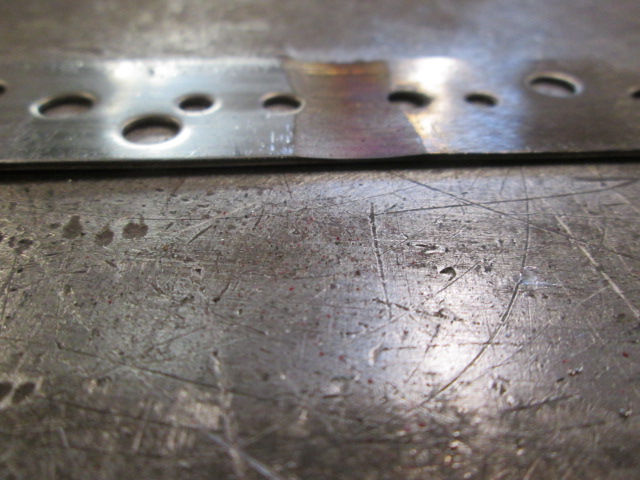
Unfortunately this occurred right in between two of the layouts, taking out two of the three extra pieces.
Okay, we’re going to have to do this the hard way. I clamped the small drop end of the parts to the bench and knocked off the burrs using a 60 grit flap disc on the 4-1/2 inch grinder.
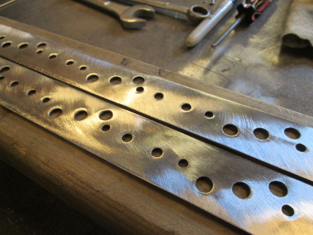
Now I could test fit a lamp w/o the burrs stripping the insulation on the wires.
Then I blocked them down some with 80 grit. Not going crazy here, just taking some of the highs down w/o thinning the material down too much.
To even things out, 100 grit on the dual action (DA) sander. This got down into the low areas to make the finish look more uniform. I didn’t go crazy trying to get every scratch out, because most of the area will be hidden under the light housings; but I did pay a little more attention to the screw tab areas that will be exposed.
Here I have buffed with a green Scotchbrite pad. Also, you can see that I did all of the final sanding operations on an aluminum plate. I didn’t want to risk dragging iron into the SS from the steel work table. You can quickly contaminate SS to the point where it will rust easily from imbedded iron.
Before cutting the parts out I shaped the first piece on one end using the remaining stock as a handle. Then I cut the first piece off and used it as a template to scribe onto the next piece. After sanding that piece to shape I cut it off and used the pair to scribe the other end onto each other. I had hoped to maintain symmetry by doing it this way, but I am just not that good using the Bader, especially since Karl never bothers to use a rest and/or vertical platen (which would be my preference and is what I am used to on other sanders).
So now that I had a couple parts with reasonably similar shaped ends, I cut the remaining blanks, stacked and bolted them all together.
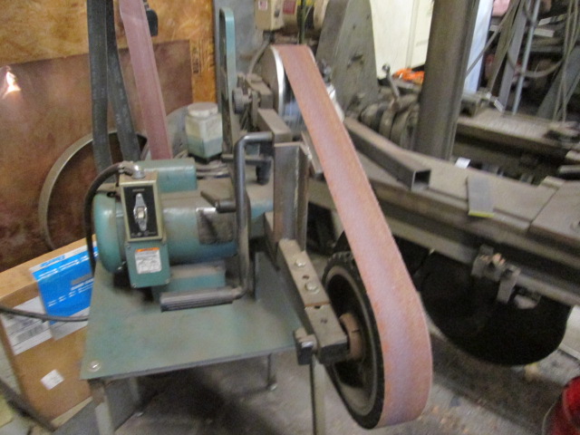
Here’s a reminder of what the Bader looks like. Note the only platen (hard backed surface) is the small backed area at the angled section on top. The other options are slack belt or over the nose of the rubber wheel. There are various attachments and options available, but this setup works for most of Karl’s needs, and I am still trying to adapt.
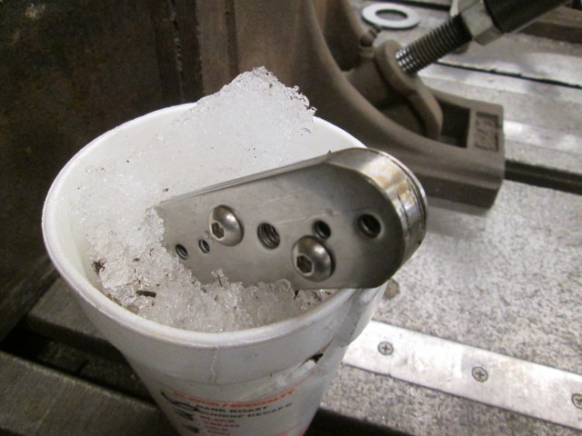
With the parts stacked I had an easier time working on edge under the nose of the wheel. Here is an in progress shot cooling things down in some ice packed snow I scooped up from outside.
Here's a quick 3:45 min video of the sanding operation. I tried to add some narration, which seemed to show up in the Movie Maker app, but wouldn't play back, nor would the soundtrack from the original video feed. Oh well. Here's another friendly tip: it's better not to sand yourself. At one point you'll see me pull my hand back and shake it a bit after nipping a cuticle and part of a fingernail. I was rolling the piece around to knock the burr off and just touched my support hand against the edge of the wheel.
https://www.youtube.com/watch?v=oYwoihhBGu0&feature=youtu.be <edited with sound levels corrected>
Almost symmetrical.
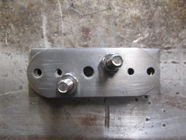
After separating the pieces; culling out the one remaining extra piece that ended up a little short; deburring the ends with 100 grit on the small hand block; and buffing again with the greenie, we get these.
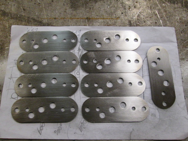
They’re not perfect, but after about 6-7 hours of coercing metal I don’t mind owning them with some small amount of pride.
Dopey me, I forgot to take a picture of a finished mount and light together. Next time.


 Hopefully we'll be able to make some spring gatherings.