The West System epoxy with 410 fairing filler behaves very much like Bondo, except it is not polyester based. So in this case, the problem is my novice technique, not the product.
High build (polyurethane?) primer would be the other option, but neither Karl or I want to spray bomb the loft (although the sanding dust is building up and making a mess anyway, it should be easier to clean up than overspray). '?' on polyurethane because I'm still not convinced on material compatibility, both backward and forward. Haven't picked sealer and top coat types yet, but I know if I stick with epoxy everything (vinyl spackle being the exception) is compatible.
Teardrops n Tiny Travel Trailersor t n ttt for short (tnttt.com) |
The Poet Creek Express - Foamie Hybrid
Moderator: eaglesdare
Re: The Poet Creek Express - Foamie Hybrid
![]() by KCStudly » Wed May 25, 2022 9:40 am
by KCStudly » Wed May 25, 2022 9:40 am
KC
My Build: The Poet Creek Express Hybrid Foamie
Poet Creek Or Bust
Engineering the TLAR way - "That Looks About Right"
TnTTT ORIGINAL 200A LANTERN CLUB = "The 200A Gang"
Green Lantern Corpsmen
My Build: The Poet Creek Express Hybrid Foamie
Poet Creek Or Bust
Engineering the TLAR way - "That Looks About Right"
TnTTT ORIGINAL 200A LANTERN CLUB = "The 200A Gang"
Green Lantern Corpsmen
-

KCStudly - Donating Member
- Posts: 9640
- Images: 8169
- Joined: Mon Feb 06, 2012 10:18 pm
- Location: Southeastern CT, USA
Re: The Poet Creek Express - Foamie Hybrid
![]() by KCStudly » Fri May 27, 2022 9:46 pm
by KCStudly » Fri May 27, 2022 9:46 pm
Bodywork is like a roller coaster ride. First you slowly work your way up the hill with anticipation of something good (all the prep work and application of the fairing filler). You get up on top and the view looks pretty good (wet filler seemed to go on okay); then things start going down hill and it looks pretty scary (once the second(?) round of filler has cured it doesn’t look as good as you thought it did when it was still wet and you have more blisters to deal with). You brace yourself (knuckle down and get tucked in to the “rework”… really just a step in the iterative process, not really rework), wave your arms around (with the long board in your hands sanding, sanding, sanding) and scream on the way back down (because your back is hurting a little bit from all of that sanding and you’re not sure what you’ve gotten yourself into). Then when the ride is over (will it ever be over?) things seem happy again (or at least things don’t seem so bad after all) and you ride the adrenaline rush for a little bit.
So catching up, on Tuesday I “braced myself” and went after those new blisters. The two smaller ones may have been there, but I deemed them small enough not to try and fix them at the time (can’t say for sure). If so, they were bigger and puffy now. The larger two were certainly not apparent previously.
Here are some pics after "filling" the blister drilled holes with neat epoxy and letting it cure.
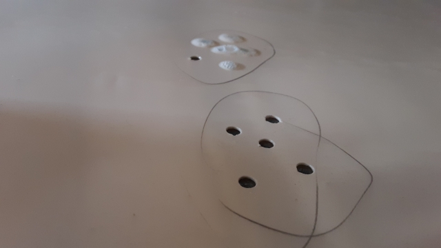
You can see how some of the holes look empty. Some are, the neat epoxy slipped down in, presumably into voids in the foam or between foam and inner wall skin. Some just look empty in the pics but are actually full. And some have erupted and crusted over where escaping air bubbled up. The air bubbles could be caused by the epoxy running down and displacing the air in the cavities (either just the drilled hole, are a larger void), or they could be from the same source that caused the blister in the weave in the first place… chemical off gassing or thermal expansion. I’m thinking not thermal expansion because filling the holes was done in the evening and ambient temperatures were falling at the time of the cure.
I’m assuming there are hidden voids because I made sure to fill the drill holes up, first by squirting the epoxy in with a syringe, then tapping on the surrounding area, then sticking a bamboo skewer down in the hole (which was too close to the size of the hole and tended to squeeze out more than it released the air, then refilling and sticking a smaller piece of wire in the hole to release more air. Either way, some holes just drained right out and no reasonable amount of epoxy would fill the hole. Some filled fine, some just partially.
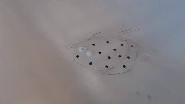
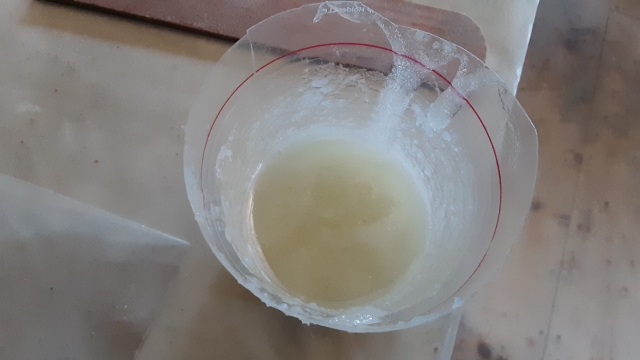
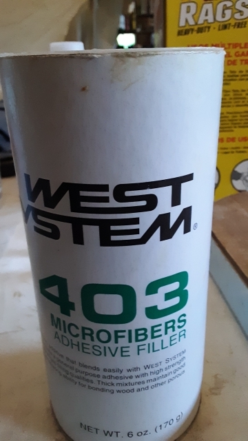
So that doesn’t seem ideal, but the loose weave was now reattached and hard again. Next step was to wash amine, scrape the blisters and high spots down and sand almost flush. Vacuumed sanding dust out of the remaining pits and mixed up a loose slurry of epoxy and 403 structural filler (little short “chopped” glass fibers). Almost the same technique to get it in the holes, except no syringe, just slop it on with the stirring stick and push it into the holes with skewer and wire.
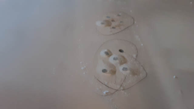
The funny looking tan-ish colored spots that you can see thru the epoxy in the last pic is where the scraper kind of dug into the fairing filler when I got a little careless. Not to worry, if the slurry doesn’t fully fill them there is going to be plenty more fairing filler in my future.
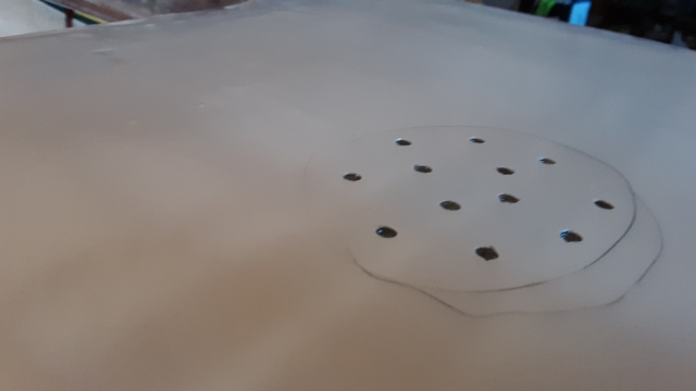
Tonight I washed these areas; sanded them down fair to the last round of built up fairing using the two different grit medium hand blocks.
Then I hit the front wall section with the long hand board to see what was what. Once I started to see the weave in a few spots I proceeded to “degloss” (break the shine off) all the areas that the long board didn’t touch.
I was encouraged by the result and took the long board to the larger rear section of the wall. The hard flat long board, which is made from 3/4 hardwood with a 1x2 strong back rib on it, has a medium grit length of sander belt on it (not paper, cloth backed). Something like 80 or 100 grit, and is just a little bit bigger and and hard to run than the slightly shorter board with coarser grit, I think maybe 36 grit. The latter is a 3/8 thk strip of plywood, so can flex a little bit if pushed, but still keeps you honest for the most part. The funny thing is that the heavy board with strong back is actually harder to run by holding the rib; it gives you leverage above the CG so it tends to flip over if the grit grabs a bit. Whereas with the plywood board you have to hold it at or near the CG and you have no leverage to flip it over, so it glides easier… not just because it is shorter and lighter.
I didn’t get all the way through with the rear section of the wall, but was encouraged by progress just the same. Will finish that step up tomorrow. The next step is to do a guide coat of primer, hit it lightly with the longer board again and decide if it’s flat enough for my taste. We’re getting close to where the sealer, primer and top coats should be able to handle most of the rest of it… on this surface, anyway.
Add another 1-1/2 hrs to the labor count for tonight, and an hour or so for Tuesday.
So catching up, on Tuesday I “braced myself” and went after those new blisters. The two smaller ones may have been there, but I deemed them small enough not to try and fix them at the time (can’t say for sure). If so, they were bigger and puffy now. The larger two were certainly not apparent previously.
Here are some pics after "filling" the blister drilled holes with neat epoxy and letting it cure.
You can see how some of the holes look empty. Some are, the neat epoxy slipped down in, presumably into voids in the foam or between foam and inner wall skin. Some just look empty in the pics but are actually full. And some have erupted and crusted over where escaping air bubbled up. The air bubbles could be caused by the epoxy running down and displacing the air in the cavities (either just the drilled hole, are a larger void), or they could be from the same source that caused the blister in the weave in the first place… chemical off gassing or thermal expansion. I’m thinking not thermal expansion because filling the holes was done in the evening and ambient temperatures were falling at the time of the cure.
I’m assuming there are hidden voids because I made sure to fill the drill holes up, first by squirting the epoxy in with a syringe, then tapping on the surrounding area, then sticking a bamboo skewer down in the hole (which was too close to the size of the hole and tended to squeeze out more than it released the air, then refilling and sticking a smaller piece of wire in the hole to release more air. Either way, some holes just drained right out and no reasonable amount of epoxy would fill the hole. Some filled fine, some just partially.
So that doesn’t seem ideal, but the loose weave was now reattached and hard again. Next step was to wash amine, scrape the blisters and high spots down and sand almost flush. Vacuumed sanding dust out of the remaining pits and mixed up a loose slurry of epoxy and 403 structural filler (little short “chopped” glass fibers). Almost the same technique to get it in the holes, except no syringe, just slop it on with the stirring stick and push it into the holes with skewer and wire.
The funny looking tan-ish colored spots that you can see thru the epoxy in the last pic is where the scraper kind of dug into the fairing filler when I got a little careless. Not to worry, if the slurry doesn’t fully fill them there is going to be plenty more fairing filler in my future.
Tonight I washed these areas; sanded them down fair to the last round of built up fairing using the two different grit medium hand blocks.
Then I hit the front wall section with the long hand board to see what was what. Once I started to see the weave in a few spots I proceeded to “degloss” (break the shine off) all the areas that the long board didn’t touch.
I was encouraged by the result and took the long board to the larger rear section of the wall. The hard flat long board, which is made from 3/4 hardwood with a 1x2 strong back rib on it, has a medium grit length of sander belt on it (not paper, cloth backed). Something like 80 or 100 grit, and is just a little bit bigger and and hard to run than the slightly shorter board with coarser grit, I think maybe 36 grit. The latter is a 3/8 thk strip of plywood, so can flex a little bit if pushed, but still keeps you honest for the most part. The funny thing is that the heavy board with strong back is actually harder to run by holding the rib; it gives you leverage above the CG so it tends to flip over if the grit grabs a bit. Whereas with the plywood board you have to hold it at or near the CG and you have no leverage to flip it over, so it glides easier… not just because it is shorter and lighter.
I didn’t get all the way through with the rear section of the wall, but was encouraged by progress just the same. Will finish that step up tomorrow. The next step is to do a guide coat of primer, hit it lightly with the longer board again and decide if it’s flat enough for my taste. We’re getting close to where the sealer, primer and top coats should be able to handle most of the rest of it… on this surface, anyway.
Add another 1-1/2 hrs to the labor count for tonight, and an hour or so for Tuesday.
KC
My Build: The Poet Creek Express Hybrid Foamie
Poet Creek Or Bust
Engineering the TLAR way - "That Looks About Right"
TnTTT ORIGINAL 200A LANTERN CLUB = "The 200A Gang"
Green Lantern Corpsmen
My Build: The Poet Creek Express Hybrid Foamie
Poet Creek Or Bust
Engineering the TLAR way - "That Looks About Right"
TnTTT ORIGINAL 200A LANTERN CLUB = "The 200A Gang"
Green Lantern Corpsmen
-
KCStudly - Donating Member
- Posts: 9640
- Images: 8169
- Joined: Mon Feb 06, 2012 10:18 pm
- Location: Southeastern CT, USA