Picture dump and progress update. Almost done… sorta.
I ended up having to cut the passenger side brake drum off using a cut off wheel in the 4-1/2 inch grinder. Basically I cut thru the rim of the drum from the backing plate to the wheel flange in two locations 180 deg apart. Due to the labyrinth seal between the drum and backing plate I couldn’t cut quite all the way thru w/o getting into the backing plate, but the drum is cast iron, so once most of the way thru I stuck a heavy screwdriver in the cut and whacked it with a hammer to snap the rest of the way. This allowed me to open the drum up enough to free the shoes and pull the drum off.
As it turns out, the shoes weren’t especially worn, but the passenger side drum was worn a lot more than the driver’s side. So my hopes to reuse these parts fell thru, and I ended up buying all new drums, shoes, and hardware kits. Just as well, but another $110 or so with a can of Brake Kleen and couple of sticks of new hard line.
Here’s the new driver’s side axle with the new shoes and spring kit installed.
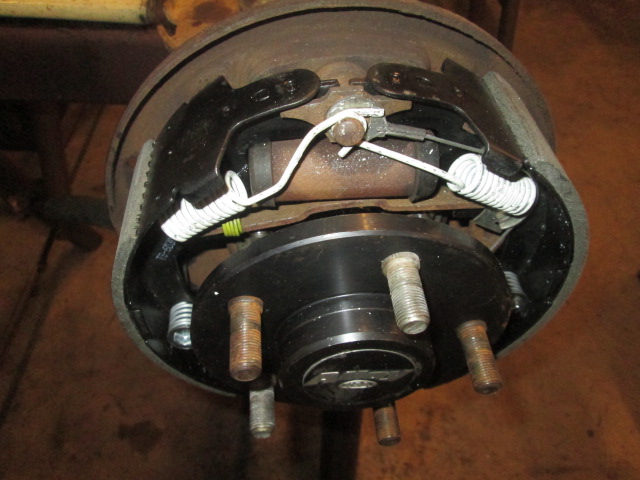
I’ve done plenty of brake jobs in my time, but hadn’t ever done one with this “modern” style of cable operated adjuster. I took plenty of pictures for reference purposes while taking the D35 apart. Still, included in the new hardware/spring kit were a couple of horse shoe shaped clips and wave washers that did not come out of the OEM assembly. I tried to search on-line to see what I was missing, apparently they weren’t important enough to warrant mention. I thought the horse shoe clips might be a throw away tool for setting the shoe retainer spring cups on the pins using vice grips, but they didn’t fit in the detents inside of the spring cups (I have the driver tool for this so used it anyway). The wave washers are still a mystery.
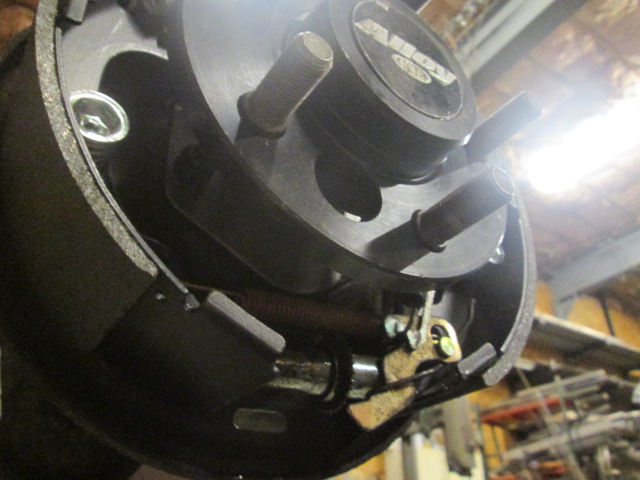
The parking brake adjuster assembly.
The street side went together fine. On the curb side I had a hell of a time with the guide sheave for the adjuster cable. It is supposed to seat under the rear shoe return spring, but the sheave kept popping out of the hole in the shoe rib as I tried to seat the cable on the post. Finally I just ignored it going over the sheave, put the loop over the post, and went ahead and installed the spring, then I was easily able to hold the cable in the sheave and pop the sheave back into the hole under the tension of spring using a screw driver. All it took was frustration, time, and a trial and error approach.
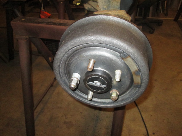
Sprayed the drum down with brake cleaner, installed it with a couple of lug nuts to hold it on squarely, and adjusted the shoes out. First out enough to really drag, almost lock, and then backed off until just dragging a little. They need to be broken in.
That was yesterday.
Today I cleaned the street side drum, installed it and adjusted the shoes.
Back inside the diff cover, since I was not able to source the locker hose or wire clamps, I moved the OEM clamp up to the bulkhead barb fitting (since it was harder to access), and twisted my own wire tie out of 1/32nd SS TIG welding wire for the locker apply piston barb.
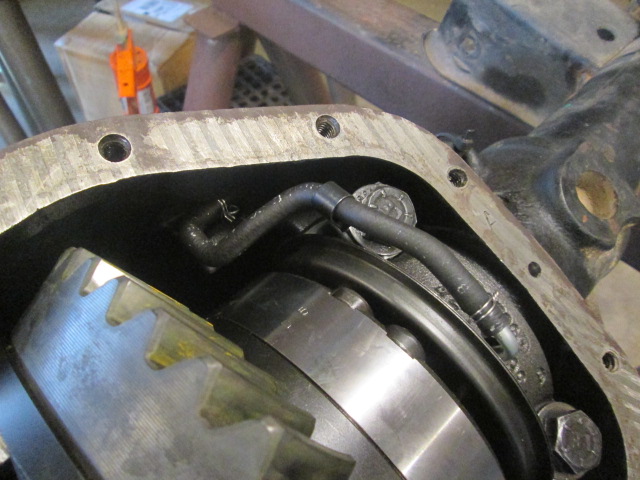
You can see the OEM clamp better here.
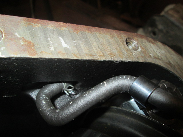
I double wrapped the wire, twisted it tight with vice grips, and trimmed it off clean with dikes (making sure to hold both of the tag ends so that they didn’t clip off and fall into the housing).
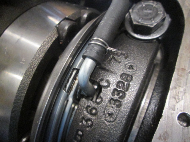
Both joints seemed to be plenty tight for the low pressure application.
If you have ever tried to squeeze 2 quarts of thick gear lube thru a rubber hose into a tiny fill plug while under your vehicle you would appreciate the total ease of removing the bottle cap and dumping it straight into the diff.
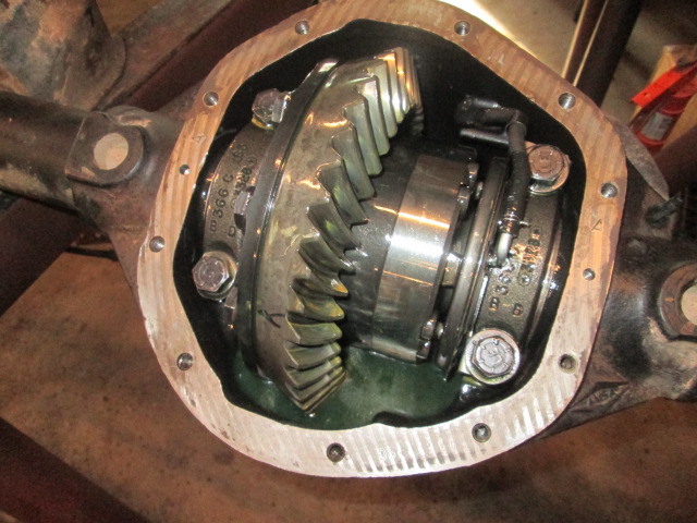
Something that totally irks me is when a guy puts a big 1/4 inch bead of sealer on a diff cover (or oil pan, or timing cover, or valve cover, etc.) and slaps the cover on. This can be quite risky if a big chunk of sealer breaks off inside and blocks an oil passage, or whatever. This is what I found on the D35 that had been serviced by the quick lube. There wasn’t any evidence of large chunks coming adrift, but there was enough squeeze out that it was dragging on the ring gear. Seriously. I get it; they don’t want call backs from people complaining that they have oil dripping in their driveways, but come on. And I am also not a fan of using just sealer instead of a gasket. In my experience the best method is a thin film of sealer on both sides of a gasket. Basically you smear the gasket on both sides leaving perhaps a 64th on both sides… just enough to color, but not so much that it is piled up.
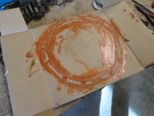
I used one of the boxes the drums came in as a pallet to smear the gasket with Ultra Copper (which I am partial to). Gloved and gooey, so no picture of the gasket, but here is what the pallet looked like after the fact.
And here is the cover bolted up.
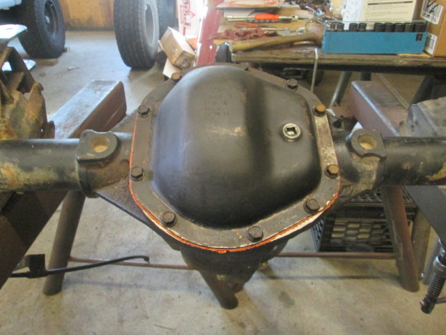
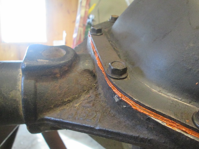
Note the very small, yet even, bead of squeeze out all the way around. It only takes a thou or so to fill any voids that the treated paper gasket doesn’t get, so unless your cover is grossly warped, more sealant is just a liability.
Oh yeah, BTW, since the dealer didn’t have the cover bolts in stock I had resolved to just reuse the mixture of OEM and Gr 8 bolts, but then when I took the D35 cover off I had a whole ‘nuther set of cover bolts at hand; so I cleaned some of those up and had a whole set of the serrated flange bolts to use. Same thing with the tube flange studs; rather than grinding a flat on the head of a replacement bolt, I just popped one of the studs out of the D35 and drove it into the flange on the D44 using a screw clamp as a press and socket as a spacer.
Here’s a look at the aftermarket panhard mount bracket. It bolts thru the OEM panhard mount bracket using an anti-crush sleeve in place of the stock panhard bar; had three (3) additional 5/16 bolts drilled thru and mounted to the factory mount; and was welded in two (2) locations to the axle tube along the bottom edge. This raised the panhard mount location several inches and rotated the angle to suit the PO’s higher lift and pinion angle required for a double cardan drive shaft CV joint… which I don’t have… so it had to go.
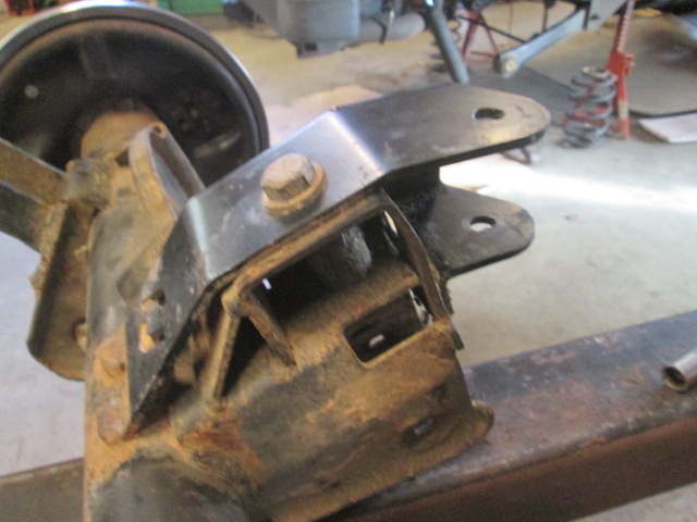
I used the cutoff wheel in the 4-1/2 inch grinder to cut the welds most of the way thru, unbolted the rest, pried it off the rest of the way, and then ground the rest of the weld beads down fair.
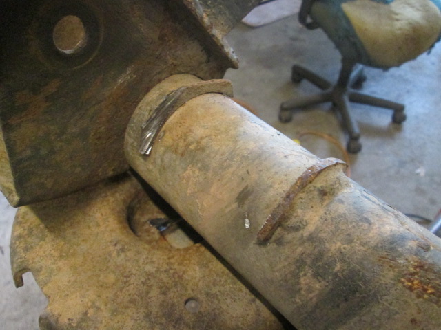
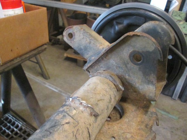
The axle also has aftermarket shock mounts. These include plates welded to the backs of the lower trailing arm mounts (boxing those in and making them stronger), and new ‘U’ brackets weld to those for the shock mounts. Best I can tell these were added to the previous vehicle while the axle was still installed. That meant that the OEM shock mounts had been crudely cut off using a recip saw, with large remnants still remaining. The new/improved lower shock mounts put the lower shock several inches out further on the axle, which in theory improves dampening (if it doesn’t change the shock geometry enough by laying it out more horizontally), but more importantly for a rotated rear, supposedly gains clearance with the springs. My concern was that if these aftermarket shock mounts don’t line up, or are of an inappropriate height for my 1-3/4 inch lift shocks, and I can’t just cut them free and rotate them on their existing plates, then I might have to resort back to OEM style shock mounts. No better time than the present to remove the original stubs and prep for this event,
Here I have already cut most of the remnants of the original shock mounts. Driver side first, then curb side.
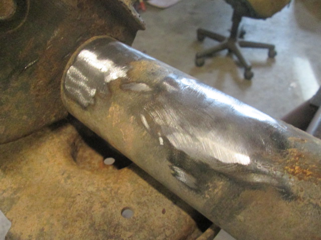
Here I have used a flap sanding disc to remove the rest of the remnants.
Next I used a putty knife and screwdriver to go around and scrape muck, dirt and grease off of all of the mounting points. There was a large amount of hardened mud packed into the anti-sway bar mounts, enough junk overall to fill a dust pan.
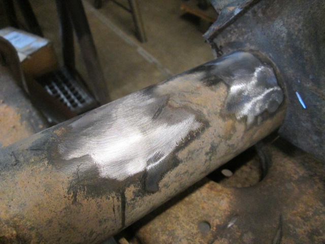
When scrapping the grease out of the inside of the upper driver’s side trailing arm mount I was surprised to find the putty knife stopping hard on something very firm. There was a big step running right thru the bolt hole axis. After cleaning this up with a wire brush and solvent I found that some prior activity had attempted to cut the trailing arm bolt using a recip saw between the trailing arm bushing and the mount flange. Probably the same ‘Primitive Pete’ that cut the axle. The mount ear had been shaved at an angle practically more than half way thru its thickness all the way thru half of the bolt hole.
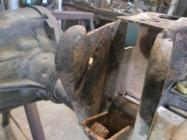
Unacceptable!
While Karl is well equipped, I don’t always know where all of his tools are, and sometimes he has much of them on the road with him. And this area was mostly inaccessible to a wheeled grinder. So I used a hand file to remove the burr off of the saw cut, opening the gouge up to accept a filler weld. I was going to weld this up using the small MIG, but Karl had just off loaded that out of the bed of his truck last night and presumably still had the shield gas regulator in the cab. So I ended up dragging the big TIG welder over and used that.
First I ran a bead right up the bottom of the cut filling that up and eliminating the sharp notch. Next I fanned a pass cladding some of the area that had been slashed away. Unfortunately when I got to the area adjacent to the bolt hole it washed away; so I let it cool and came back from the outside and filled it in on the edge of the hole using less heat. By building up a large bead of excess filler on the outside of the bolt hole, I was able to go back in from the inside, where the torch angle was not ideal, and fill the rest from the inside. One or two more passes to clad the inside, paying particular attention to the area around the hole where the bushing will bear, and a little make up on the top edge to fill in the under cutting from the first pass there, a lot of hand filing where the flap wheel couldn’t reach, and we get this.
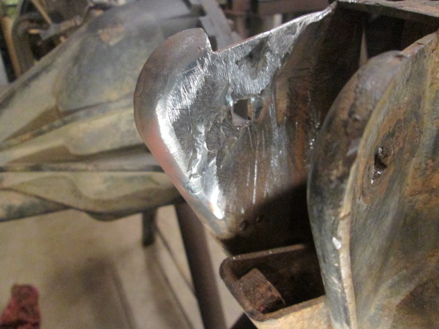
Not pretty, but way better. A little more filing to square the bolt hole back up and she is good enough. Hell, she was in use before, but I could just not leave it like that for fear that the ear would tear right off at the stress riser.
Formed new brake hard lines. Particular attention paid to avoiding any rub spots, like around the spring perches. This was harder than it sounds; the factory bends were much tighter than either of my bending tools and I didn’t want to cave the tubing in. It always seems that I have trouble forming the double flared ends. Even the good quality Rigid brand tube clamp I have doesn’t want to clamp the small tubing hard enough that it doesn’t just push thru the flaring clamp tool. Eventually I found the technique that worked using a combination of my double flaring mandrel and press, and Karl’s clamp. The trick seemed to be to put a really good chamfer on the inside of the tiny 3/16 inch tube ID before attempting to form the first bubble.
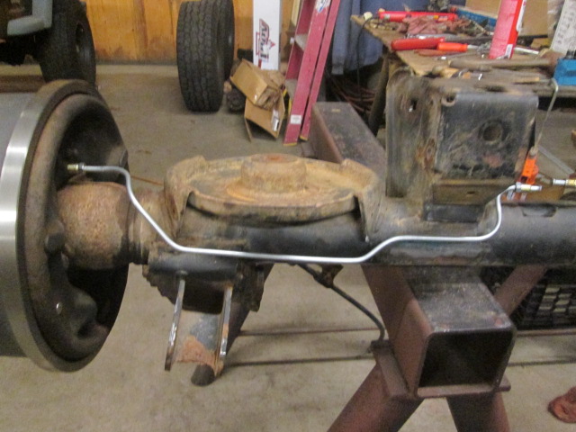
The clamp adjacent to the passenger side upper trailing arm mount is attached with screws that are threaded straight thru the axle tube, so I smeared some sealant around these holes and bolts before securing, and made sure to slip the OEM rubber sleeve over the tube before forming the new end. This is right where the exhaust passes over the axle, too, so should be good for clearance with the exhaust pipe.
If I remember I will pick up some high heat black paint on the way out tomorrow. The brake drums and hard lines will look and last that much better with a little paint on them… nothing fancy, just a quick spray.
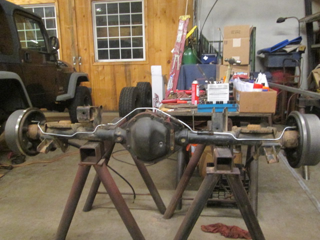
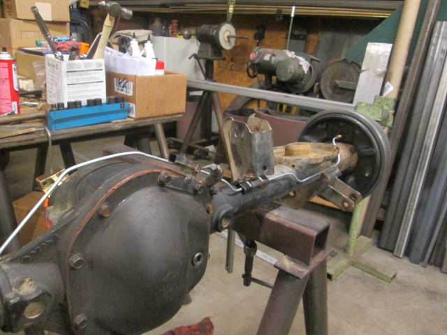
Just need to wipe road debris and grease off of the panhard bar, and get that loosely bolted to the axle mount before installation.
Hopefully everything will go relatively smoothly tomorrow and it will be back drivable. Hopefully.