Too much information? Well maybe this is something that I have always had great respect for, but never had the confidence to attempt myself until now. I’ve been a gearhead most of my life but haven’t had the experience, necessary equipment, or need until now; so why not dive right in? I guess there is some latent confidence from my experience rebuilding mixing equipment and working with truly professional machinists that I just want to share out of a sense of pride. On the other hand it could be doubt. I mean, this still seems new to me. The mixer equipment is somewhat forgiving and frequently maintained, so the level of precision required to obtain a long gear life, quiet operation, and reliable service in this application is a step above for me. Who else to share with but interested friends? Even if they are internet friends, they are still interested friends, right?
Maybe it is just you and me, Tom?
No matter, but yes, it is a lot of work that requires a good deal of attention to details, so I am confident that I can pull it off!
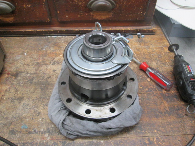
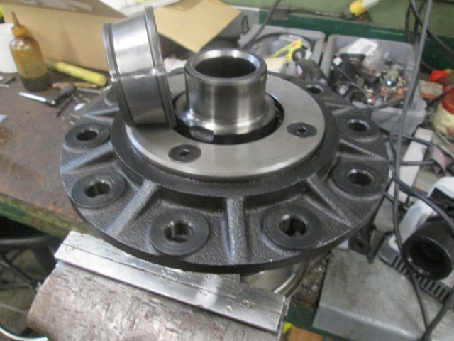
Finally some pics! Catching up first, this is the TFS locker (with worm gear pinions to provide anti-slip traction when unlocked). You can see how I have already removed the cage and rollers from the ‘opposite side’ carrier race, and how the locker apply piston assembly can be removed.
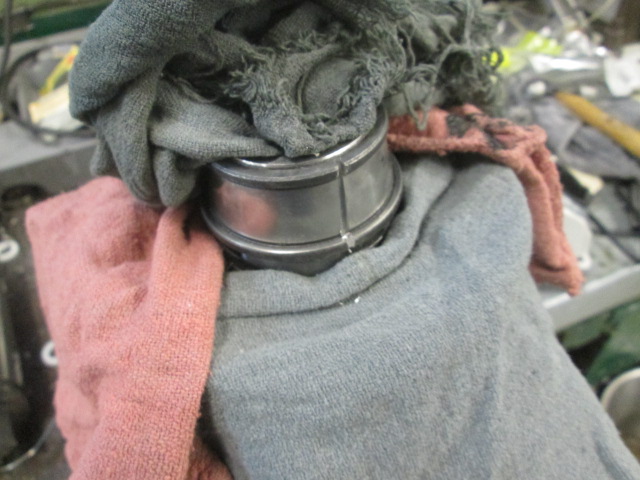
Here is the apply piston after wiping it down. The bolt flanges get pinched between the opposite side carrier bearing cap bolt washers and cap and the air tube connects via molded rubber air tube thru a bulkhead fitting in the housing.
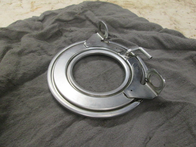
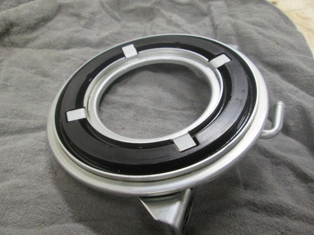
This tin flange moves axially from the thrust when the apply piston bladder inflates, engaging the locker mechanism. The rim of the tin flange also engages the button on the locker engage switch plunger, providing power to light an indicator on the dash telling the operator that the locker has engaged.
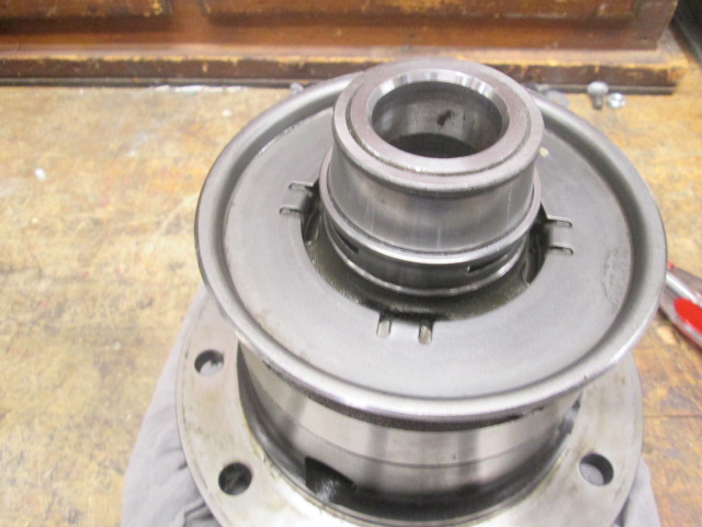
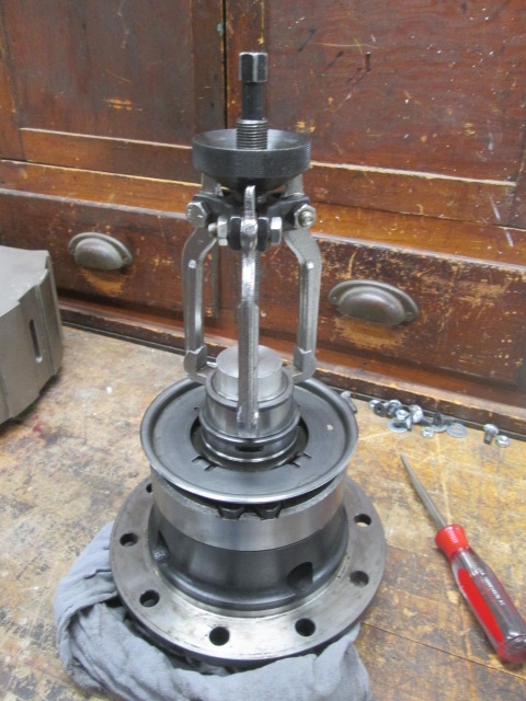
This was the first puller setup that I tried, but it was woefully under sized. Still, you can see where the jaws are grabbing under the lip of the inner race, and how I have placed an aluminum puck over the axle hole to give the puller something to jack against (the jacking thread is hidden behind the middle jaw). I didn’t take many additional pictures of this operation after this, but the solution ended up using a larger bearing splitter grabbing the same lip, and a much bigger 2-jaw puller pulling on the bearing splitter after adding the reliefs in the inner race.
Part of the solution was adding relief cuts into the race and chiseling a break to remove the interference. (Also note that I am using aluminum soft jaws and/or scraps of aluminum to clamp the carrier safely in the vise.)
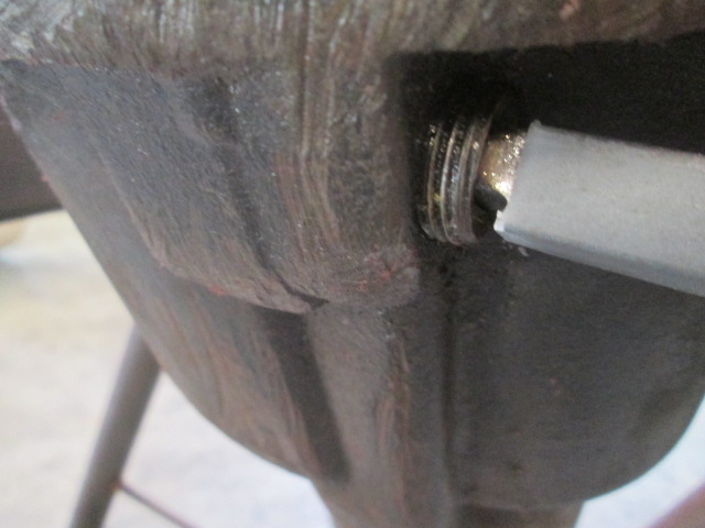
Back at Karl’s today, the previous owner dragged this rearend over a few rocks. Also note the square drive drain plug.
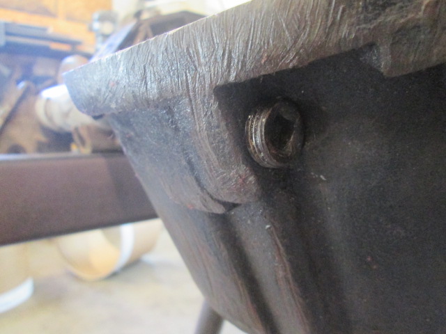
The dragging raised a burr under the edge of the diff cover. Here I have started to remove the burr using a bastard cut flat file, as evident by the shiny line around the edge.
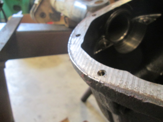
Burr removed.
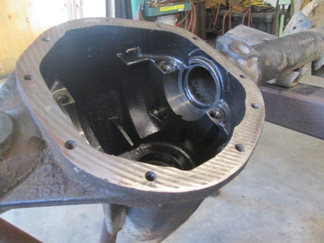
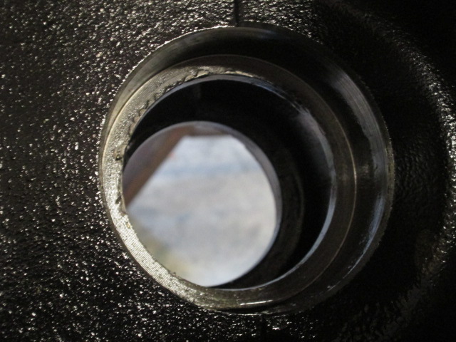
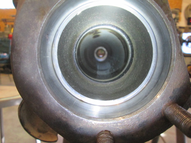
Here’s a first look inside of the housing prior to cleaning. The D44 is recognizable by the warped stop sign hexagonal shape. Note the air tube barb on the upper right hand side; below that is the mushroom headed stem of the locker engage indicator switch; and below that is the pinion inner bearing race seat.
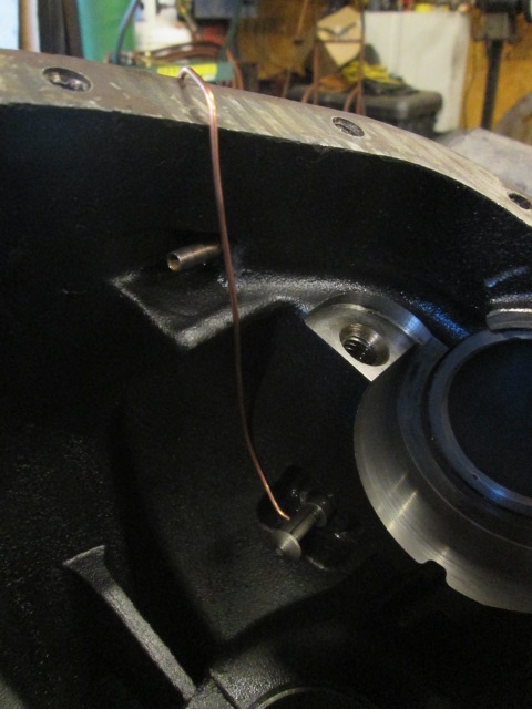
Here’s a little closer look at the air tube and locker switch shaft.
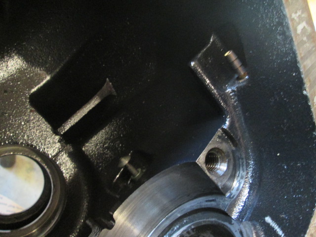
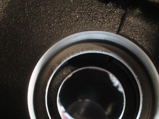
Here’s a close up of the pinion inner bearing cup seat, and something I was not happy to see. Prior activity punching out a race disturbed the cast metal around the bore causing a raised burr (from about 8:30 to 12:30 clockwise in this pic). I could tell that this was not from Karl and me driving the latest race out because the burr tips were all flattened from the last race crushing them in service. No beuno. Raised burs here would tend to cock the race, and, as the burr settles in under the point load, would tend to allow the pinion mesh with the ring gear to change, increasing clearances (bad), and also affecting the pinion bearing preload (loosening the preset between the inner and outer pinion bearings… bad).
I decided to let that simmer in my thoughts, considering my options while I worked on cleaning up the housing and the associated small parts, including the carrier bearing caps, fasteners, and diff cover. Repair options included doing nothing (unacceptable!); bringing the housing to work and having one of the qualified machinist set it up and take a cleaning pass (potentially altering the pinion depth baseline… not a super big deal, but time consuming and somewhat risky); or hand working the raised material down.
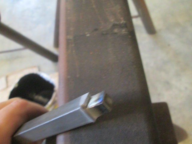
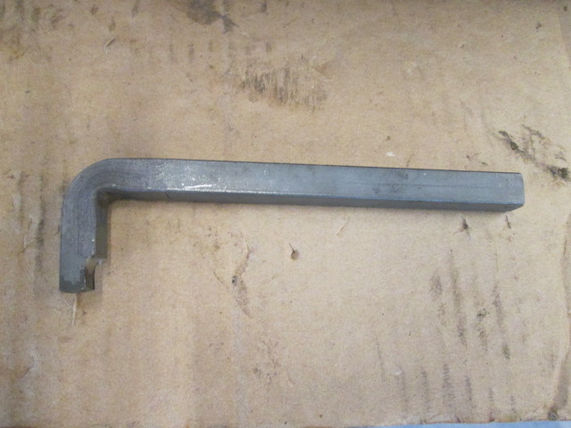
I decided to also busy myself making a square drive wrench to turn the drain and fill plugs out (never mind my mild embarrassment when Karl returned and reminded me that I could have just used a 3/8 drive socket extension on a ratchet…oh well). All I could find in the drop rack was a piece of 1/2 inch square bar. I cut slivers off two sides using the bandsaw and bent the end using the break press feature on the iron worker. It only took a few minutes and worked well in the end, so not a total loss.
I had picked up a large squirt bottle of cleaner/degreaser and spent a great deal of time ragging out the housing trying to get all of the metal debris from the broken spider gears. It seemed to just keep coming. Before getting too far along Karl helped me decide to hand work the problem area of the inner pinion bearing seat. Rather than just rubbing on it with a scrap of sandpaper and risking altering the bearing bore and/or chasing highs and lows altering the seat, I made a hard sanding block to fit half of the bore (allowing me to still hold the block with my fingers down in the hole).
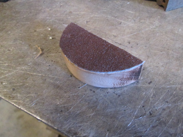
I took the raised stuff down until it started to clean the phonographic tool marks from the original machining and no farther. The burrs still look a little high in this pic, but I have been bitten before by cleaning down into the phonographic marks and losing a proper fit. It is certainly an improvement from what it was and I’m confident that I didn’t make it worse.
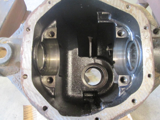
Not sure if you can see the difference, but here is the housing after thoroughly cleaning.
To clean out the axle tubes I wadded up a shop rag soaked with the degreaser, stuffed it into the tube from the center, and pushed it thru using the broom handle from the opposite side.
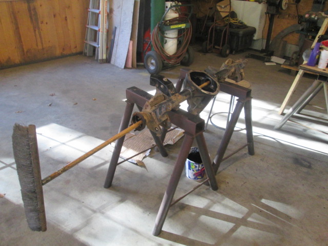
This took several passes, a lot of spraying, and the compressed air gun to shoot the rag lint out, but eventually I got it to where no more metal flakes appeared (the dark marks inside the tubes are discoloration from where the suspension brackets were welded onto the outside). I also wire brushed the ends of the tube flanges and bearing retainer stud threads.
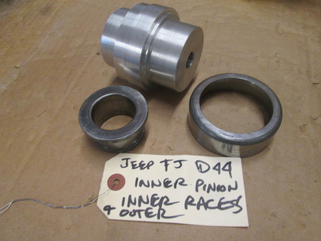
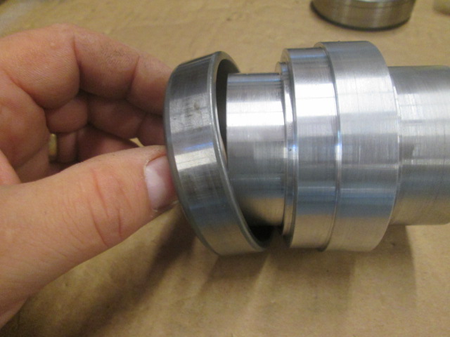
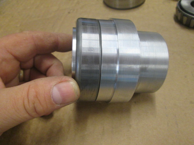
Here’s what’s left of the old inner pinion bearing and the aluminum driver that I mentioned.
Starting the new inner pinion bearing race into the housing bore.
Driving the inner pinion bearing race. The weight slug on the slide hammer was too big around and would have hit the carrier bearing saddle, so I just used a ball peen hammer on the end of the slide hammer shaft and it worked fine.
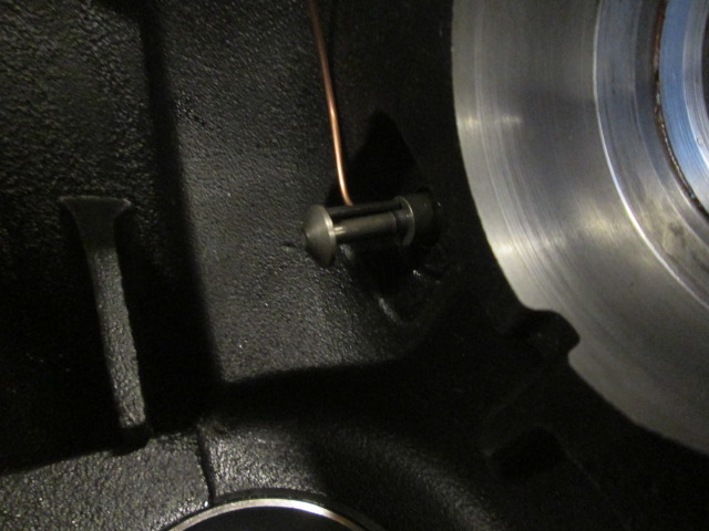
Here you can see the seated race (at the bottom of pic) as well as a better pic of the locker indicator switch shaft.
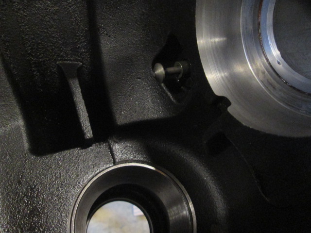
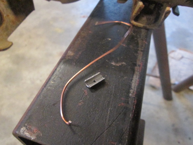
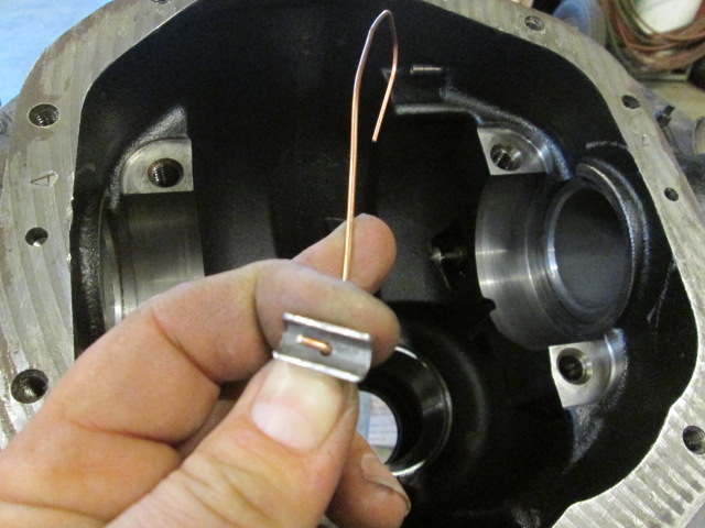
One of the tricks to dealing with these rear ends is avoiding damaging the switch shaft. The switch shaft must be extended when the carrier is dropped in otherwise the disc might not engage the shaft properly and may even break it. The trick is to wedge something under the button of the shaft to hold it in the extended position, and yet have a lanyard attached so that the wedge can be retrieved w/o becoming lost in the housing. A common method is to tie a string around a length of small diameter dowel, however, I did not have any string handy, nor dowel of the proper diameter. So I used a piece of steel tube, similar to brake line, cut in half lengthwise and to the proper length. I deburred this thoroughly, drilled a small 1/16 hole in the middle, and fashioned a piece of welding wire to act as a lanyard hooked over the outside of the housing.
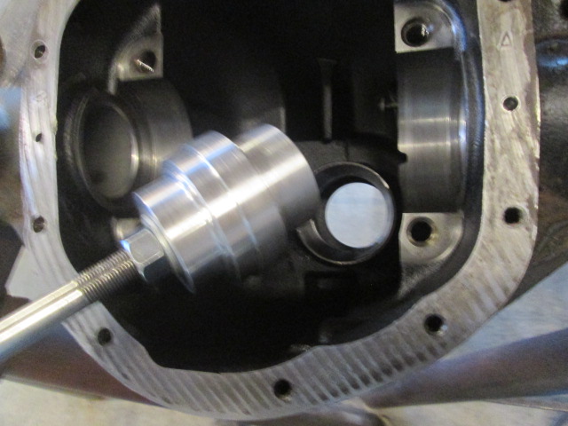
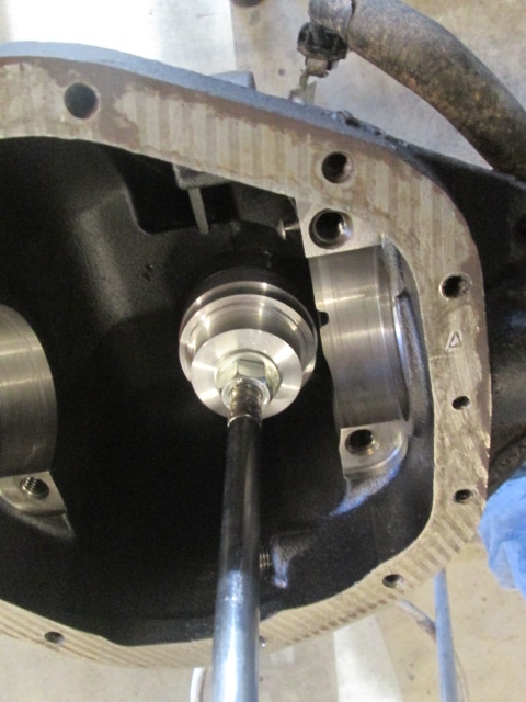
This allowed me to drop (more correctly, to place) the carrier, with 4.10 ring gear temporarily bolted and carrier bearing cups, into the housing in order to measure the side thrust clearance.
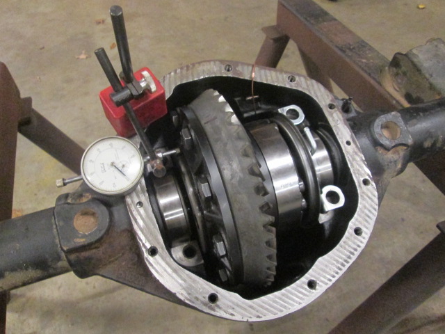
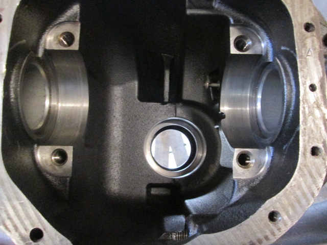
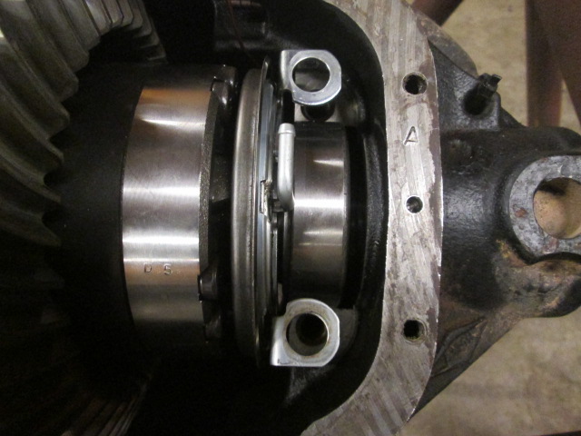
The Spicer factory manual for the “generic” D44 says to pick and mark one of the ring gear bolts, and use a flat surface thereon to indicate off of. It also says to repeat this measurement until you get a consistent result within 0.002 inch. Well this is pretty ridiculous as there are quite a few raised markings on the bolt heads and the rest is just not that flat. However, on the locker case there are a couple of machine turned surfaces, so I used one of those instead. This gave a very consistent 0.002 runout when checked all the way around (rotating the carrier past the indicator) and 0.001 repeat on zero after thrusting the carrier back and forth, using a couple of flat blade screwdrivers to reach down into the gap at the bearing race preloading it in either direction. In this pic of the ‘opposite’ side you can see the ring gear on the left; the shiny part of the carrier cap that holds the differential worm gears and other magic inside; the locker flange and apply piston; the shiny outer race of the opposite side carrier bearing; and the thrust gap between that and the end of the passenger side axle tube boss. It is this gap that we are trying to accurately measure.
This measurement gives us the total carrier shim stack that will be divided on either side once we add the pinion and determine how this clearance needs to be divided. In order to preload the bearings and prevent the gears from flexing apart, we need to add between 0.010 and 0.015 inch extra shim (the factory manual calls for 0.015 inch all added to the opposite side, thus splitting the difference and providing about 0.0075 lash; while other internet sources allow 0.010). The indicator indicated 0.258 total thrust. I measured the carrier bearing shims that came out of the 5.13 gear setup and found them to be 0.130 on the gear side and 0.140 on the opposite side, which totals at 0.270 inch, or about 0.012 inch preload; right in range.
The actual shim thickness for either side of the carrier will be determined once the pinion has been installed. We’ll repeat this measurement with the ring gear thrust up against the pinion and compare the difference.
Assuming that we get the pinion depth set right the first time (ha ha), we should get proper backlash, and a good mesh pattern; then we can set the final pinion preload. More likely, the pattern will be off and we will have to adjust the pinion depth shim (hence the need for an easily removable inner pinion setup bearing), which will throw the carrier shims off. And so we will iterate until all of these factors are fat, dumb and happy. There is no room for TLAR here; it must be more or less exact!
 ).
).