Teardrops n Tiny Travel Trailersor t n ttt for short (tnttt.com) |
The Poet Creek Express - Foamie Hybrid
Moderator: eaglesdare
Re: The Poet Creek Express - Ooh, The Suspense
![]() by KCStudly » Fri Apr 13, 2012 10:09 am
by KCStudly » Fri Apr 13, 2012 10:09 am
On top of all of those ideas we could write the whole thing off as an unreimbursed training expense. I wonder how Mike would feel about becoming accredited.
KC
My Build: The Poet Creek Express Hybrid Foamie
Poet Creek Or Bust
Engineering the TLAR way - "That Looks About Right"
TnTTT ORIGINAL 200A LANTERN CLUB = "The 200A Gang"
Green Lantern Corpsmen
My Build: The Poet Creek Express Hybrid Foamie
Poet Creek Or Bust
Engineering the TLAR way - "That Looks About Right"
TnTTT ORIGINAL 200A LANTERN CLUB = "The 200A Gang"
Green Lantern Corpsmen
-

KCStudly - Donating Member
- Posts: 9613
- Images: 8169
- Joined: Mon Feb 06, 2012 10:18 pm
- Location: Southeastern CT, USA
Re: The Poet Creek Express - Miles of Welding
![]() by KCStudly » Sat Apr 14, 2012 8:31 pm
by KCStudly » Sat Apr 14, 2012 8:31 pm
The brown truck cometh.
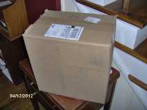
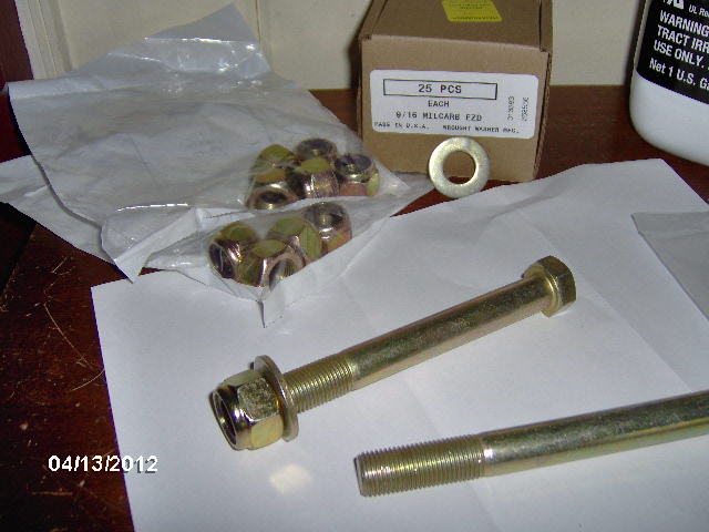
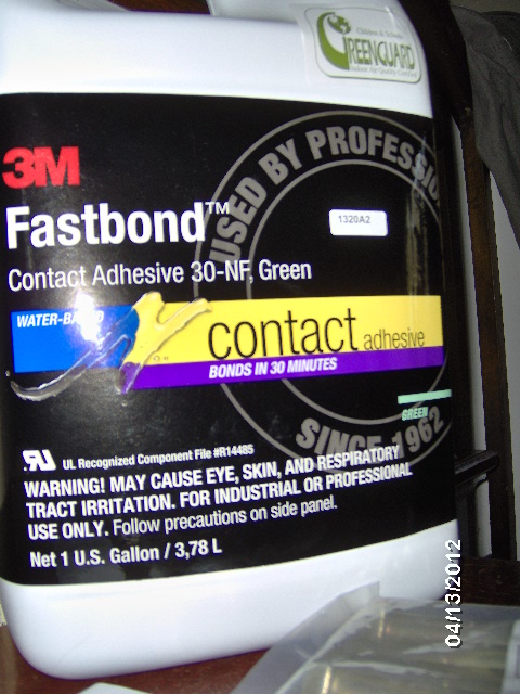
Suspension hanger hardware and a gallon of 3M Fastbond 30NF Green water based contact adhesive.
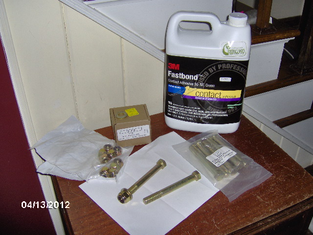
Grade 8 hardware.
30NF
Well I managed to get 2 out of 3 tax forms complete and with the Fed holiday on Monday I had no problem getting away for the day to thrash. With the shop to myself for the weekend I jumped right in with a little warm up welding on the tongue box mounting clips. First I did the flat bar clamp up thing.
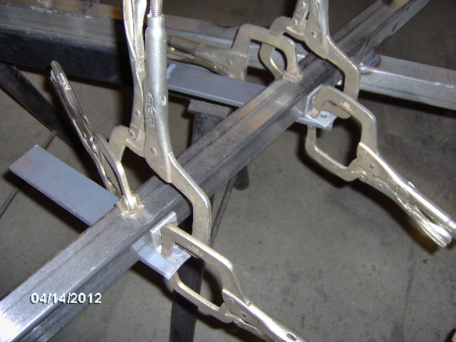
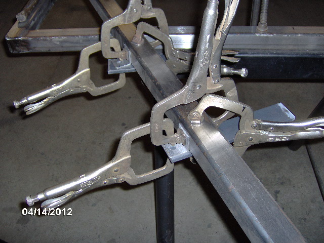
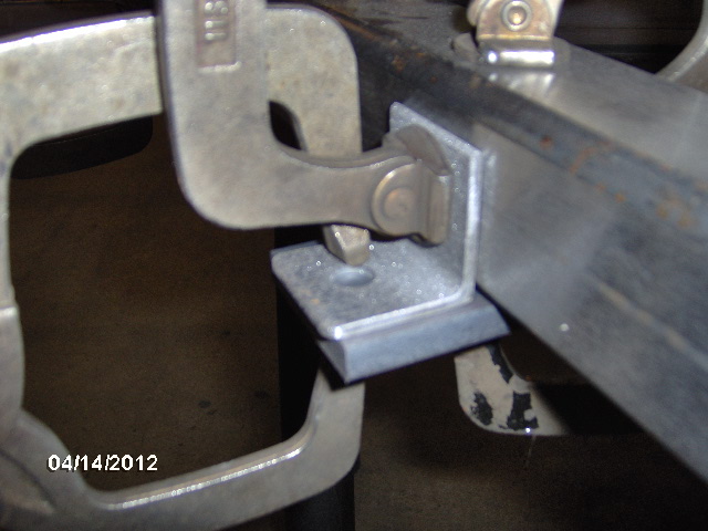
Tack 4 corners.
And weld 3 sides.
Wash, rinse, repeat.
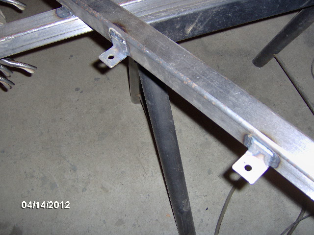
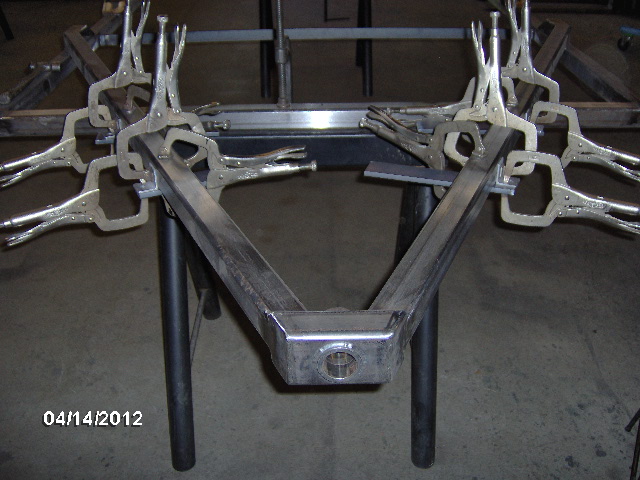
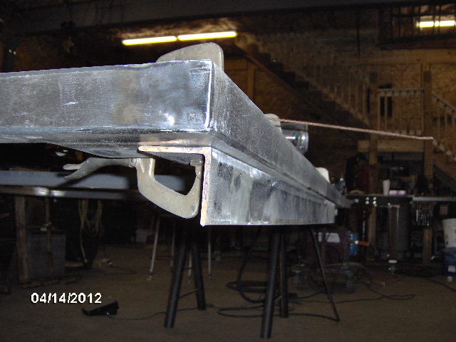
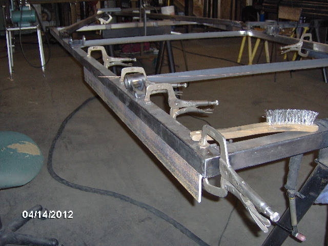
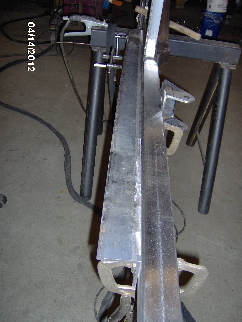
Looking down the frame side rail you can see the warping that has occurred due to welding on the tongue and spring hangers so far.
It's going to happen.
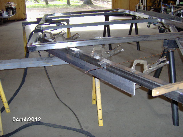
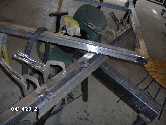
In order to try and minimize this I clamped on a piece of angle as a strong back, about 4 ft long, onto the frame spanning the hanger areas to be welded.
Breakfast of Champions.
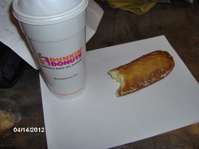
Gotta stay nourished.
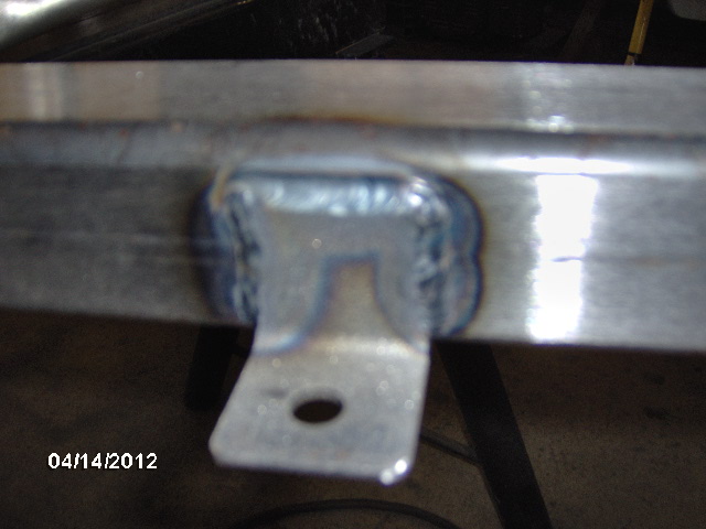
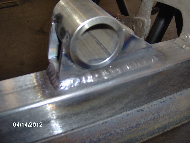
Welded the outside of the street side shackle hanger.
That ain't coming off.
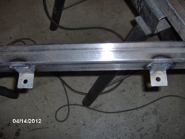
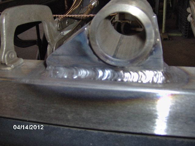
I had two pieces of angle and kept hopscotching them around so I could leave one on until it cooled fully while still moving on to the next location. Here is the curb side shackle hanger with strong back in place.
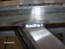
And here is the curb side shackle hanger outside weld.
That ain't coming off either.
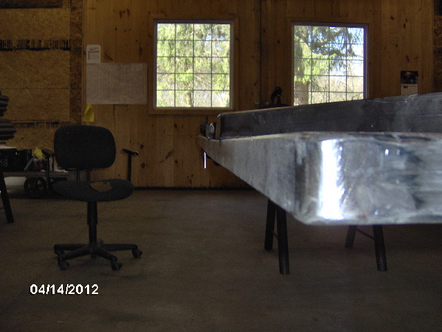
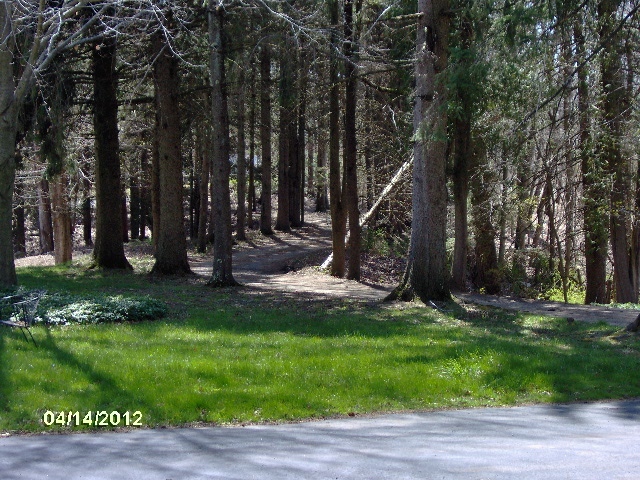
It was a beautiful day at the shop,
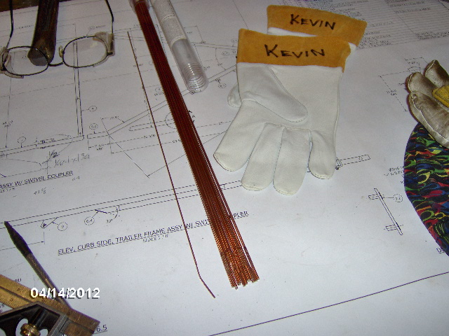
and I was running low on 3/32 welding rod.
Karl had said that he had plenty of welding rod in inventory, but I didn't know where it was and needed an excuse to get out into the sunshine, so I made a run to here,
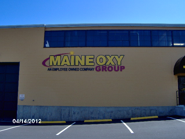
for another pound of rod and some new gloves.
Stopped at a do drop in for a bacon cheese burger on the way back.
The Brown Derby
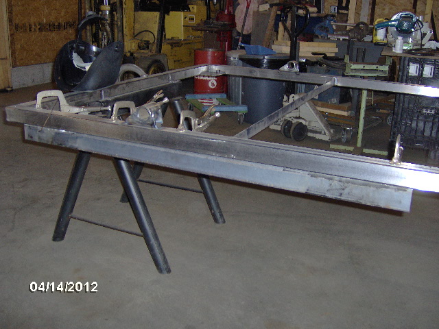
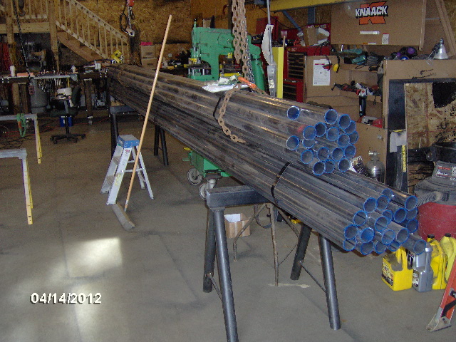
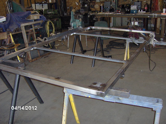
The Zamboni de-icer job is going to use a lot of pipe which was sitting on a couple of the shop saw horses.
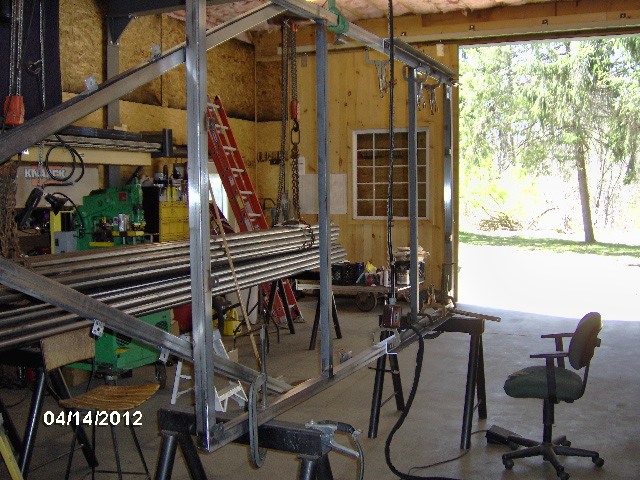
So I had been using just the remaining two heavy horses clamped along the front and rear xmbr's. When I went to reposition the frame to avoid out of position welding, I had to shift the horses to one side first. Easy enough to hang one side off of the hoist, pick up one corner and the next to reposition the horses to one side.
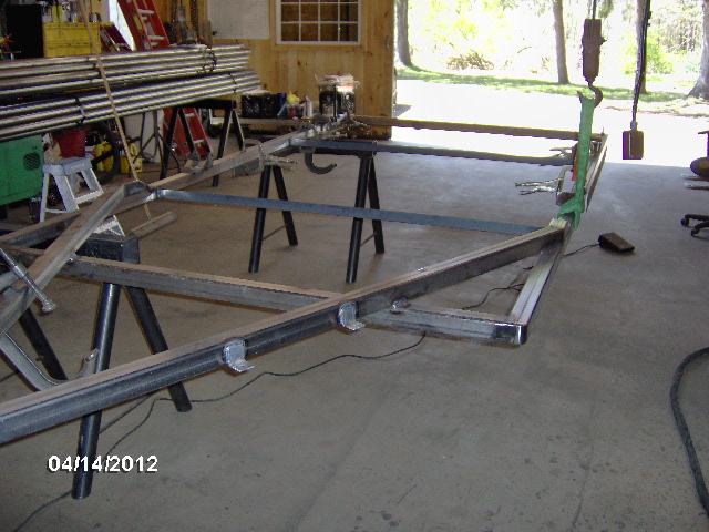
Then hoist it up and clamp it back down on the horses.
Sure is nice not having to plan out my flips too carefully. Miss a weld or screw up the sequence and it's not hardly any trouble to lift it up and flip it again. It's not too bad to handle with two people, but it is almost effortless with the hoist.
Here's the street side shackle hanger inside with strong back in place prior to welding.
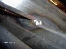
While welding this joint I think I must have lifted off a little and got a small bit of porosity. Out with the grinder and safety gear. Safety first: safety glasses with side shields, hearing protection, full face shield and gloves.
Took care of that no problem and here is the finished weld.
While that weld was cooling I cut four gusset blanks from some 1/4 x 1 flat bar scrap.
If you look closely you can see the scribe line on the one that is clamped over the side of the bench.
And here is a posed photo with the cutoff wheel after nipping off the corner.
And here are the four after nipping the inside corner (to clear the hanger-to-frame weld), rounding the outside corners a bit and breaking the edges on the Bader belt sander.
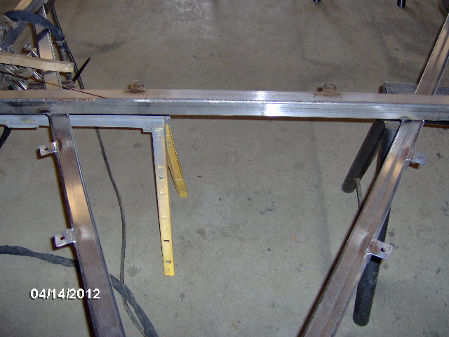
Before moving on to the front spring hangers I repositioned the strong back to straddle the area to be welded. Most of the frame warping was located around the front hanger where I had previously welded it at the front and rear "undersides". So I clamped the strong back on to the rear first and measured the gap at the other end.
5/16 inch out over approx. a 25 inch spread.
This strong back was a little thinner stock than the other one so when I clamped it the rest of the way it pulled to the frame instead of the other way around.
Well at least it was pulling back some in the right direction.
Inside street side front spring hanger prior to welding.
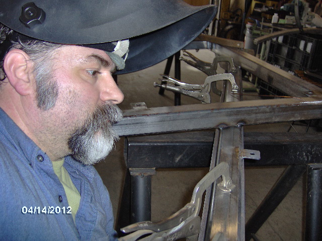
And here I am afterward enjoying a "welding Zen moment".
Using a little scrap of box tube to square and clamp up the first hanger gusset.
And here it is fully welded.
The little black spot is just a speck of soot or something, not a flaw.
Wash, rinse, repeat for the 2nd gusset.
Here's the inside of the street side rock slider and tongue to main frame joint prior to and after welding. Note the strong back is still in place.
After it cooled I popped the front clamps back off of the strong back and the measurement was down to 3/16 inch over 25. Better. Will probably try to bend it back to straight after all welding is done. Will consult with Karl. Probably stick one end under the fork truck counterweight, block up the middle where
the bend is, and weight down the opposite end until it springs back true.
Reposition the frame again, now right side up.
A little cattywampus on the odd horses, but it'll do.
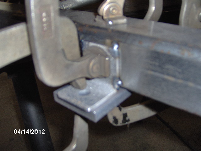
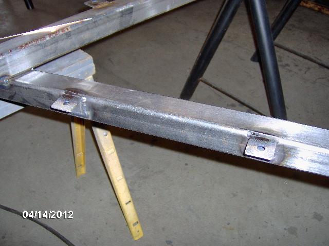
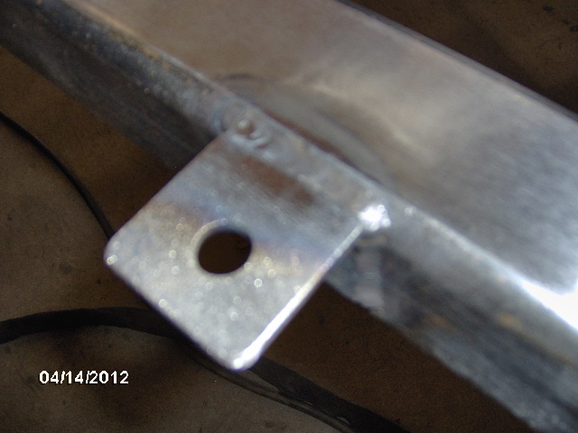
Welded the tops of the tongue box mounting clips.
Switched to the heavy strong back and moved it to straddle the tongue rail to front xmbr joint.
Welded the tongue rail to the front xmbr curb side front and rear, including wrapping the corners closed.
This side was relatively easy because I am right handed; had to climb into the middle of the front of the frame to get the back.
Added another heavy strong back to the other side.
Welded street side front and rear. Note the wrap visible in the 2nd pic.
Had to squeeze into the tongue area to gain position on this one. Back of the chair was outside and I was perched on the edge of it so that I could fit down to where I could see the puddle.
Reposition the frame again. This time I'll be welding on the "top" (curb side side), so I set it down on the floor. Needed to weld near where the rigging strap was so it had to come off, lest it melt. Made sure to clamp the frame well to the horses.
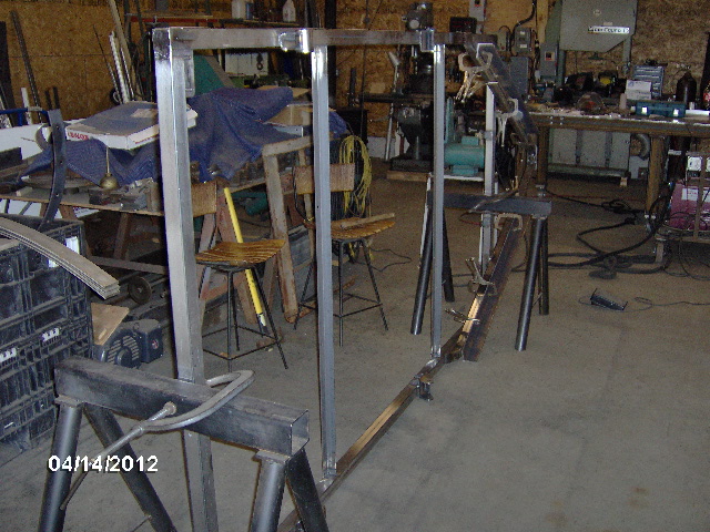
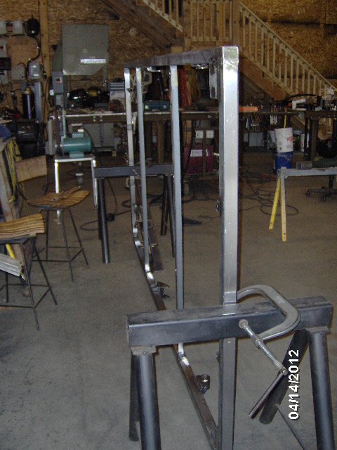
In this position the weld was right about at my eye level, and it would be very difficult, if not impossible to operate that TIG foot pedal while standing on my tippy toes. Hmmm, small step ladder? No not enough of a base; not going to stand on a ladder on one foot. How about these drop cuts from some heavy planks? Perfect!
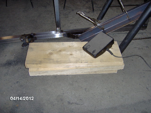
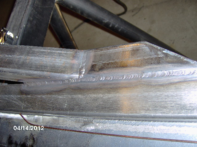
And here is the curb side slider outside weld that resulted.
This took me to about 4:15pm so it was time to split so I could get home and watch the drag race qualifying. Once you get a whiff of nitromethane you are hooked for life!
Suspension hanger hardware and a gallon of 3M Fastbond 30NF Green water based contact adhesive.
Grade 8 hardware.
30NF
Well I managed to get 2 out of 3 tax forms complete and with the Fed holiday on Monday I had no problem getting away for the day to thrash. With the shop to myself for the weekend I jumped right in with a little warm up welding on the tongue box mounting clips. First I did the flat bar clamp up thing.
Tack 4 corners.
And weld 3 sides.
Wash, rinse, repeat.
Looking down the frame side rail you can see the warping that has occurred due to welding on the tongue and spring hangers so far.
It's going to happen.
In order to try and minimize this I clamped on a piece of angle as a strong back, about 4 ft long, onto the frame spanning the hanger areas to be welded.
Breakfast of Champions.
Gotta stay nourished.
Welded the outside of the street side shackle hanger.
That ain't coming off.
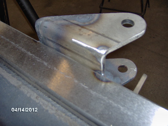
I had two pieces of angle and kept hopscotching them around so I could leave one on until it cooled fully while still moving on to the next location. Here is the curb side shackle hanger with strong back in place.
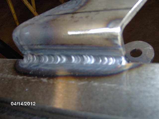
And here is the curb side shackle hanger outside weld.
That ain't coming off either.
It was a beautiful day at the shop,
and I was running low on 3/32 welding rod.
Karl had said that he had plenty of welding rod in inventory, but I didn't know where it was and needed an excuse to get out into the sunshine, so I made a run to here,
for another pound of rod and some new gloves.
Stopped at a do drop in for a bacon cheese burger on the way back.
The Brown Derby
The Zamboni de-icer job is going to use a lot of pipe which was sitting on a couple of the shop saw horses.
So I had been using just the remaining two heavy horses clamped along the front and rear xmbr's. When I went to reposition the frame to avoid out of position welding, I had to shift the horses to one side first. Easy enough to hang one side off of the hoist, pick up one corner and the next to reposition the horses to one side.
Then hoist it up and clamp it back down on the horses.
Sure is nice not having to plan out my flips too carefully. Miss a weld or screw up the sequence and it's not hardly any trouble to lift it up and flip it again. It's not too bad to handle with two people, but it is almost effortless with the hoist.
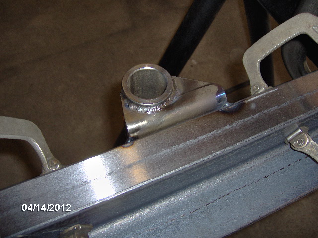
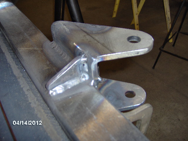
Here's the street side shackle hanger inside with strong back in place prior to welding.
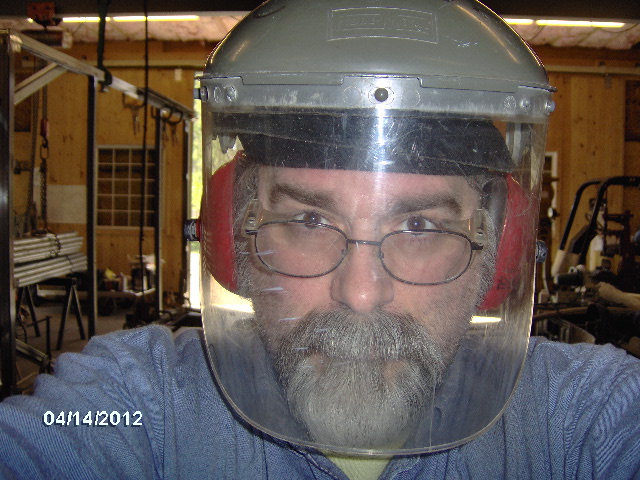
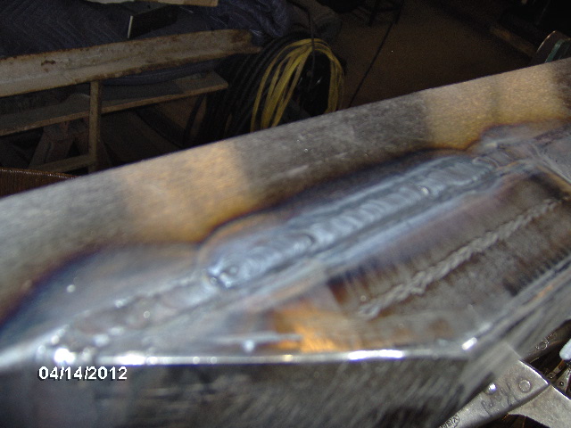
While welding this joint I think I must have lifted off a little and got a small bit of porosity. Out with the grinder and safety gear. Safety first: safety glasses with side shields, hearing protection, full face shield and gloves.
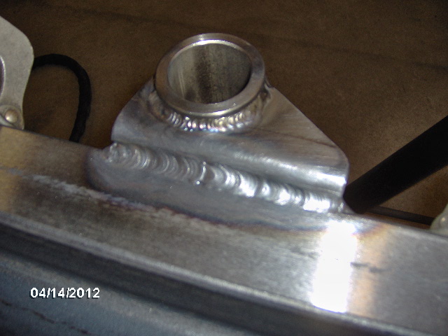
Took care of that no problem and here is the finished weld.
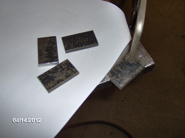
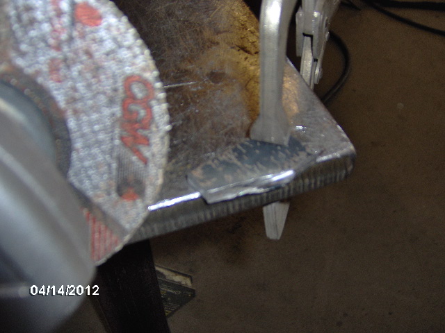
While that weld was cooling I cut four gusset blanks from some 1/4 x 1 flat bar scrap.
If you look closely you can see the scribe line on the one that is clamped over the side of the bench.
And here is a posed photo with the cutoff wheel after nipping off the corner.
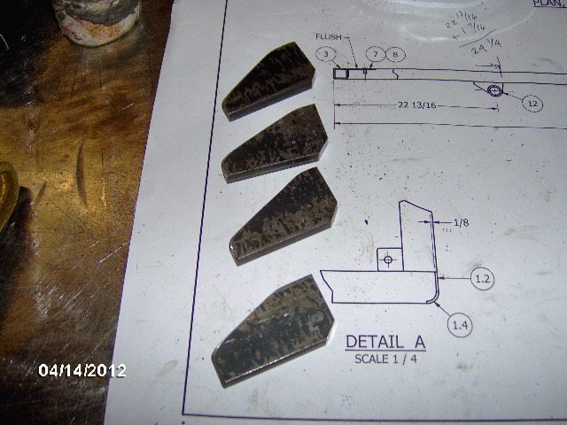
And here are the four after nipping the inside corner (to clear the hanger-to-frame weld), rounding the outside corners a bit and breaking the edges on the Bader belt sander.
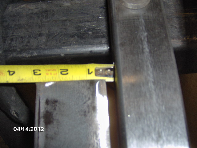
Before moving on to the front spring hangers I repositioned the strong back to straddle the area to be welded. Most of the frame warping was located around the front hanger where I had previously welded it at the front and rear "undersides". So I clamped the strong back on to the rear first and measured the gap at the other end.
5/16 inch out over approx. a 25 inch spread.
This strong back was a little thinner stock than the other one so when I clamped it the rest of the way it pulled to the frame instead of the other way around.
Well at least it was pulling back some in the right direction.
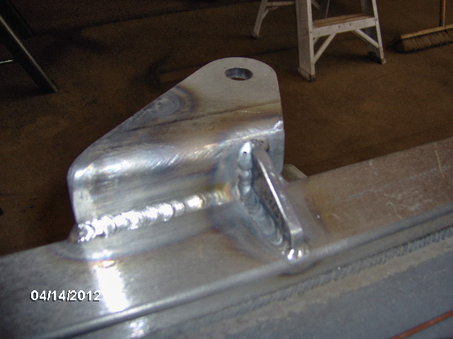
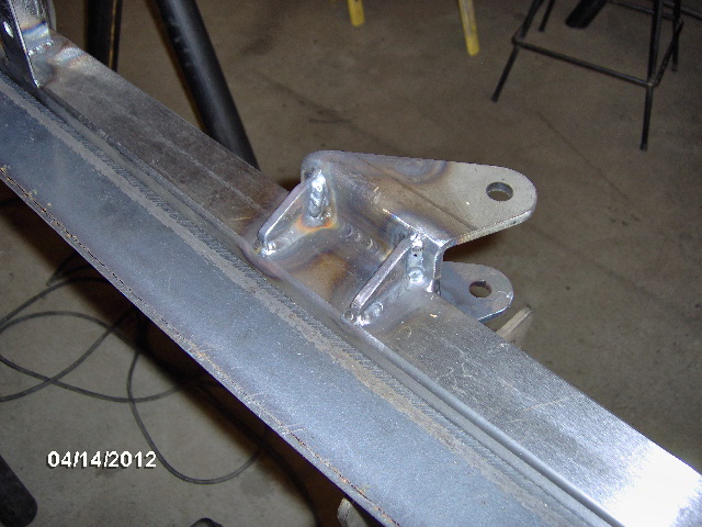
Inside street side front spring hanger prior to welding.
And here I am afterward enjoying a "welding Zen moment".
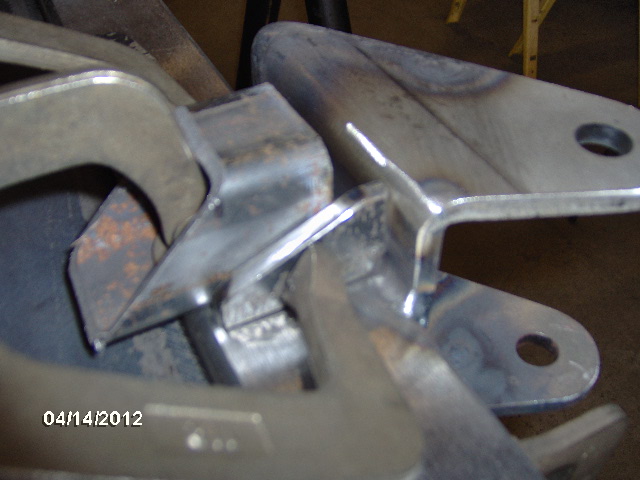
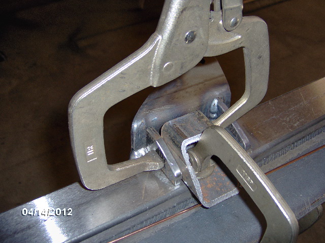
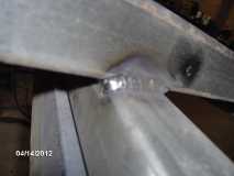
Using a little scrap of box tube to square and clamp up the first hanger gusset.
And here it is fully welded.
The little black spot is just a speck of soot or something, not a flaw.
Wash, rinse, repeat for the 2nd gusset.
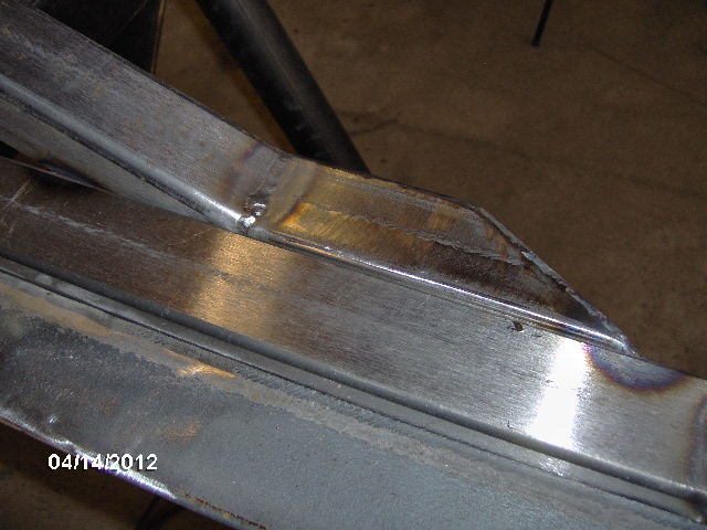
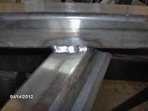
Here's the inside of the street side rock slider and tongue to main frame joint prior to and after welding. Note the strong back is still in place.
After it cooled I popped the front clamps back off of the strong back and the measurement was down to 3/16 inch over 25. Better. Will probably try to bend it back to straight after all welding is done. Will consult with Karl. Probably stick one end under the fork truck counterweight, block up the middle where
the bend is, and weight down the opposite end until it springs back true.
Reposition the frame again, now right side up.
A little cattywampus on the odd horses, but it'll do.
Welded the tops of the tongue box mounting clips.
Switched to the heavy strong back and moved it to straddle the tongue rail to front xmbr joint.
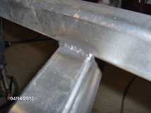
Welded the tongue rail to the front xmbr curb side front and rear, including wrapping the corners closed.
This side was relatively easy because I am right handed; had to climb into the middle of the front of the frame to get the back.
Added another heavy strong back to the other side.
Welded street side front and rear. Note the wrap visible in the 2nd pic.
Had to squeeze into the tongue area to gain position on this one. Back of the chair was outside and I was perched on the edge of it so that I could fit down to where I could see the puddle.
Reposition the frame again. This time I'll be welding on the "top" (curb side side), so I set it down on the floor. Needed to weld near where the rigging strap was so it had to come off, lest it melt. Made sure to clamp the frame well to the horses.
In this position the weld was right about at my eye level, and it would be very difficult, if not impossible to operate that TIG foot pedal while standing on my tippy toes. Hmmm, small step ladder? No not enough of a base; not going to stand on a ladder on one foot. How about these drop cuts from some heavy planks? Perfect!
And here is the curb side slider outside weld that resulted.
This took me to about 4:15pm so it was time to split so I could get home and watch the drag race qualifying. Once you get a whiff of nitromethane you are hooked for life!
Last edited by KCStudly on Fri Nov 16, 2012 6:47 pm, edited 2 times in total.
KC
My Build: The Poet Creek Express Hybrid Foamie
Poet Creek Or Bust
Engineering the TLAR way - "That Looks About Right"
TnTTT ORIGINAL 200A LANTERN CLUB = "The 200A Gang"
Green Lantern Corpsmen
My Build: The Poet Creek Express Hybrid Foamie
Poet Creek Or Bust
Engineering the TLAR way - "That Looks About Right"
TnTTT ORIGINAL 200A LANTERN CLUB = "The 200A Gang"
Green Lantern Corpsmen
-
KCStudly - Donating Member
- Posts: 9613
- Images: 8169
- Joined: Mon Feb 06, 2012 10:18 pm
- Location: Southeastern CT, USA