I posted this same question on the DIYsolar forum and so far that hasn't gone well. My fault, the picture led to some confusion. So I will attempt to explain a little more so all hell doesn't break out and maybe an experienced electronics person can help answer the original question.
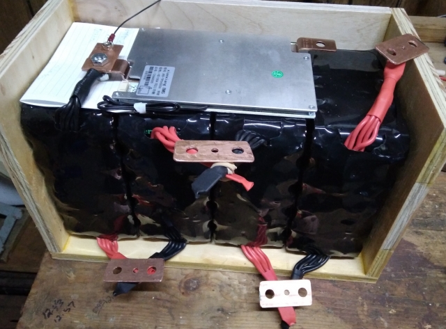
This is a mock up of a 4S LiFePo4 battery bank and a BMS. The only wire from the batteries that has an exposed end is a negative wire from battery #1. I didn't, won't, would never, ever think about connecting any of the positive battery wires until I am sure the mock up is correct.
The black wire on the left (with paper in back of it to show it clearly), which is effectively the negative terminal of these cylindrical cells, is attached to a copper plate and the BMS B- post. The small wire also attached to that copper plate is wired through a second 3/16" hole. The other connections mocked up just have a copper plate laying near the (+ and -) terminals from each cell as in a "normal" 4S configuration. The C- BMS terminal is on the upper right end of the BMS and the negative lead from the battery will connect there. The red wire from battery #4 is the positive lead from the battery. These two will be attached to battery posts on the case.
Thanks, Tim