So first, I want to say I am diving in with basically 0 electrical experience (besides being struck by lightning once!)
I am about to spend all of March making some detailed scale models of a very involved and longer term build project. see: http://www.tnttt.com/viewtopic.php?f=40&t=62268
I need to design this so that it retains full access to wiring as it will be a working prototype. I need suggestions on how to layup channels, tubes and access points to do this.
Unfortunately I only have the month of March to get as far as I can to present this model for a yay or nay towards getting funding to take the concept bigger or move on. So big time crunch!
I need to physically model all the parts, including electrical in detail in my 3D software and that takes time as well as exact measurements in order to print the model out in plastic on a 3D printer/some laser and some shopbot 3axis.
WHAT I NEED:
Please direct me to images that will allow me both a eagle level view as well as a close up view of just were all these wires are being put as well as some of the most common BEST PRACTICES.
I really need to keep things accessible and need to build this into the prototype to allow for hacking later by people doing things to add lighting FX and Arduino Boards etc.
Imagine these teardrops being designed to circle around and create a light show while sharing an electronic controller board to control the lights and sharing a large portable power source.
Think "Burning Man Art Camp" and you get an idea of the festival culture and conditions this is being designed to handle.
How to Future Proof access to your Wiring in a First Build?
17 posts
• Page 1 of 2 • 1, 2
How to Future Proof access to your Wiring in a First Build?
![]() by GreenViking » Fri Feb 27, 2015 6:01 pm
by GreenViking » Fri Feb 27, 2015 6:01 pm
-

GreenViking - Teardrop Advisor
- Posts: 66
- Images: 0
- Joined: Tue Oct 06, 2009 4:08 pm
- Location: AZ/CA
Re: How to Future Proof access to your Wiring in a First Bui
![]() by capnTelescope » Wed Mar 04, 2015 9:57 am
by capnTelescope » Wed Mar 04, 2015 9:57 am
Hi GreenViking,
I had the same concern when I started my build. Based on my experience with modern automotive electrical design, I came up with some solutions that should get you going. They will give you some flexibility to change your mind and upgrade in the future.
Weather-satellite overview
The modern automobile is full of tiny controllers (think Arduino). Sensors such as switches, photocells, etc. go into the controller, and the controller turns on/off lights, motors, etc. Easier said than done, but highly do-able. To do all this, separate wiring runs to/from each device to the controller. At first, the "controller" can just be a wiring panel.
Preliminary Planning
Decide where your controller is going to go. This needs to be physically accessible. Two obvious choices are tongue box or galley.
Plan out what electrical goodies you want. Decide both where they go and what they need in terms of switches or other sensors and wiring. For example: You want a dome light in the cabin ceiling with switches by both doors. At this point, don't worry about how you are going to wire it up. You just need to know how many wires. You need 2 wires to the light, and 2 wires for each of the switches.
Now you can plan your wiring runs.
More stuff to think about
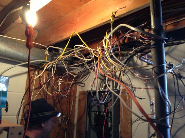
You're going to end up with a lot of wires going hither and yon. I planned my build this way, and it has about 500 feet of wires. You're going to have to think about some color coding or labeling.
I'll get some links to specific posts up here soon.

I had the same concern when I started my build. Based on my experience with modern automotive electrical design, I came up with some solutions that should get you going. They will give you some flexibility to change your mind and upgrade in the future.
Weather-satellite overview
The modern automobile is full of tiny controllers (think Arduino). Sensors such as switches, photocells, etc. go into the controller, and the controller turns on/off lights, motors, etc. Easier said than done, but highly do-able.
To do all this, separate wiring runs to/from each device to the controller. At first, the "controller" can just be a wiring panel.Preliminary Planning
Decide where your controller is going to go. This needs to be physically accessible. Two obvious choices are tongue box or galley.
Plan out what electrical goodies you want. Decide both where they go and what they need in terms of switches or other sensors and wiring. For example: You want a dome light in the cabin ceiling with switches by both doors. At this point, don't worry about how you are going to wire it up. You just need to know how many wires. You need 2 wires to the light, and 2 wires for each of the switches.
Now you can plan your wiring runs.
More stuff to think about
You're going to end up with a lot of wires going hither and yon. I planned my build this way, and it has about 500 feet of wires. You're going to have to think about some color coding or labeling.
I'll get some links to specific posts up here soon.
Last edited by capnTelescope on Wed Mar 04, 2015 11:28 am, edited 1 time in total.
-

capnTelescope - Lifetime member
- Posts: 1222
- Images: 368
- Joined: Sun Jun 27, 2004 3:44 pm
- Location: Round Rock, TX


 depending on the software version.
 blood pressure is volts and the volume of flowing blood is amps.
 . I am leaving lots of room/hackability for future possibilities/uses in the area of what micro trailers as a platform can become the base for, and particularly in the area of serving the needs beyond camping rural areas.
 It does provide much insight!