How to Future Proof access to your Wiring in a First Build?

Anything electric, AC or DC

How to Future Proof access to your Wiring in a First Build?

Postby GreenViking » Fri Feb 27, 2015 6:01 pm

So first, I want to say I am diving in with basically 0 electrical experience (besides being struck by lightning once!)

I am about to spend all of March making some detailed scale models of a very involved and longer term build project. see: http://www.tnttt.com/viewtopic.php?f=40&t=62268

I need to design this so that it retains full access to wiring as it will be a working prototype. I need suggestions on how to layup channels, tubes and access points to do this.

Unfortunately I only have the month of March to get as far as I can to present this model for a yay or nay towards getting funding to take the concept bigger or move on. So big time crunch!
I need to physically model all the parts, including electrical in detail in my 3D software and that takes time as well as exact measurements in order to print the model out in plastic on a 3D printer/some laser and some shopbot 3axis.

WHAT I NEED:
Please direct me to images that will allow me both a eagle level view as well as a close up view of just were all these wires are being put as well as some of the most common BEST PRACTICES.
I really need to keep things accessible and need to build this into the prototype to allow for hacking later by people doing things to add lighting FX and Arduino Boards etc.

Imagine these teardrops being designed to circle around and create a light show while sharing an electronic controller board to control the lights and sharing a large portable power source.
Think "Burning Man Art Camp" and you get an idea of the festival culture and conditions this is being designed to handle.
User avatar
GreenViking
Teardrop Advisor
 
Posts: 66
Images: 0
Joined: Tue Oct 06, 2009 4:08 pm
Location: AZ/CA

Re: How to Future Proof access to your Wiring in a First Bui

Postby capnTelescope » Wed Mar 04, 2015 9:57 am

Hi GreenViking,

I had the same concern when I started my build. Based on my experience with modern automotive electrical design, I came up with some solutions that should get you going. They will give you some flexibility to change your mind and upgrade in the future.

Weather-satellite overview
The modern automobile is full of tiny controllers (think Arduino). Sensors such as switches, photocells, etc. go into the controller, and the controller turns on/off lights, motors, etc. Easier said than done, but highly do-able. :) To do all this, separate wiring runs to/from each device to the controller. At first, the "controller" can just be a wiring panel.

Preliminary Planning
Decide where your controller is going to go. This needs to be physically accessible. Two obvious choices are tongue box or galley.

Plan out what electrical goodies you want. Decide both where they go and what they need in terms of switches or other sensors and wiring. For example: You want a dome light in the cabin ceiling with switches by both doors. At this point, don't worry about how you are going to wire it up. You just need to know how many wires. You need 2 wires to the light, and 2 wires for each of the switches.

Now you can plan your wiring runs.

More stuff to think about
You're going to end up with a lot of wires going hither and yon. I planned my build this way, and it has about 500 feet of wires. You're going to have to think about some color coding or labeling.

I'll get some links to specific posts up here soon.

:beer:
Last edited by capnTelescope on Wed Mar 04, 2015 11:28 am, edited 1 time in total.
I'll burn that bridge when I come to it.

Brad
ImageImageImage

Building the Bed & Breakfast
User avatar
capnTelescope
Lifetime member
 
Posts: 1222
Images: 368
Joined: Sun Jun 27, 2004 3:44 pm
Location: Round Rock, TX

Re: How to Future Proof access to your Wiring in a First Bui

Postby capnTelescope » Wed Mar 04, 2015 11:27 am

capnTelescope wrote:I'll get some links to specific posts up here soon.


So here ya go:

This post covers what all I did to install the wires from the devices to the "controller" panel.
base wiring

This post shows the wiring panel 1.0 The last picture shows the wiring panel. The electrical connections are conventional Old School for now. Arduino ready. What you see, top to bottom, Battery charger, switches from voltage to devices, device +12V connections (mostly lighting), ground connections, fuse block. The big black hose-looking thing is the wiring bundle coming out of the wall.
I'll burn that bridge when I come to it.

Brad
ImageImageImage

Building the Bed & Breakfast
User avatar
capnTelescope
Lifetime member
 
Posts: 1222
Images: 368
Joined: Sun Jun 27, 2004 3:44 pm
Location: Round Rock, TX
Top

Re: How to Future Proof access to your Wiring in a First Bui

Postby aggie79 » Wed Mar 04, 2015 11:37 am

Please let me start by issuing the disclaimer that I'm neither an electrician nor an RV tech. That said, wiring the teardrop was not my first rodeo. Also, I don't have a clue about controllers, so we'll leave Brad and others to comment on the technical aspects. I hope you find the photos and comments helpful.

In the first pictures, you see wiring Hades. For the average teardrop, I did go a little overboard on my electrical systems. (There's a total of three - 12 VDC trailer (vehicular) lighting, 12 VDC outlets, lighting and accessories, and 120 VAC outlets, lighting and accessories.) From the first picture, I'd direct attention to the schematics I have taped on the galley. Draw your schematics before you start. Even if you don't know specifics, plan your distribution chases, termination points, etc. Not visible in the picture is each end of the wiring is individually labeled at both ends to identify the circuit. Also, what is not readily visible are the chases I provided in my cabinetry for the wiring. I wish I had better pictures but I don't. All of the 120 VAC wiring was completely enclosed in conduit or chases. Most of the 12 VDC wiring was too. Exiting from the conduit and/or chases the last part of the runs for a few of my low voltage/signal wiring was exposed. When this happened I did make sure that these runs were secured to a surface by clamps.

Image

Image

Image

Image

The second photo shows the lower left hand galley cabinet. You can see the three electrical systems. The terminal blocks are for my trailer lighting. The cabling on the right is 120 VAC and the cabling on the left is 12 VDC. It is best to keep the systems separate until they are at an area where they need to converge. Two things that are visible, which are not best practices are I mixed 12 VDC trailer lighting wiring in with the 120 VDC wiring, and my 12 VDC wiring is white and black cabling rather than black and red.

Image

Underneath the trailer is another place to route your wiring. In the above photo, you can the wiring comes from the floor/deck of the teardrop. The next two photos show the conduit/sealtight runs for the 12 VDC and 120 VAC wiring from the front to the back of the teardrop.

Image

Image

Image

The last photo shows the near complete "wiring closet" in my lower galley cabinet. Note a couple of things. The space on the floor is for a 12 V battery inside a battery box. The "port" on the outer wall is the vent for the battery. The orange switch is a disconnect for the battery. (It disconnects both "legs" of the battery. It has four positions - off, battery 1, battery 2, and battery 1 + battery 2). You'll also see the abundance of terminal blocks. Instead of daisy chaining outlets, accessories, etc., I made individual runs to each device (+ and - on the DC side, and hot, neutral, and ground on the DC side). They are "tied" electrically at the terminal blocks. The 12 VDC terminal block has an automotive style blade fuse for each run.

Image

This may be overkill to make individual runs but it did prove beneficial. I did have a short in the DC side that I could not find out what was the problem for the longest time. It was for the "halo" lighting underneath the teardrop. It turns out that I had a defective switch. Having this on a separate fused circuit allowed me to remove the blown fuse and keep using the rest of the system until I tracked down the problem.

Also, the above photo doesn't shown the finished wiring - my cabling was much neater - and doesn't show the Plexiglas covers for the terminal blocks that I made.

Hope this provides a little insight.

Take care,
Tom
Tom (& Linda)
For build info on our former Silver Beatle teardrop:
Build Thread

93503
User avatar
aggie79
Super Duper Lifetime Member
 
Posts: 5405
Images: 686
Joined: Tue Aug 07, 2007 5:42 pm
Location: Watauga, Texas
Top

Re: How to Future Proof access to your Wiring in a First Bui

Postby capnTelescope » Wed Mar 04, 2015 12:23 pm

Confuse-us say: Picture worth wordy explanation:
Image :?

Note: "Wordy explanation" directed at my first post above, not Tom's. :D
Last edited by capnTelescope on Wed Mar 04, 2015 10:46 pm, edited 2 times in total.
I'll burn that bridge when I come to it.

Brad
ImageImageImage

Building the Bed & Breakfast
User avatar
capnTelescope
Lifetime member
 
Posts: 1222
Images: 368
Joined: Sun Jun 27, 2004 3:44 pm
Location: Round Rock, TX
Top

Re: How to Future Proof access to your Wiring in a First Bui

Postby MtnDon » Wed Mar 04, 2015 2:20 pm

Very nice wiring job Tom! :thumbsup:
Our 6x12 deep vee nose cargo trailer camper conversion... viewtopic.php?f=42&t=58336

We have a small off grid cabin we built ourselves in the NM mountains; small PV solar system; 624 watts PV, Outback CC & inverter/charger ... http://countryplans.com/smf/index.php?topic=2335.0
User avatar
MtnDon
2000 Club
2000 Club
 
Posts: 2200
Images: 24
Joined: Sun Aug 19, 2012 10:57 pm
Location: New Mexico
Top

Re: How to Future Proof access to your Wiring in a First Bui

Postby GreenViking » Wed Mar 04, 2015 9:05 pm

Thank you Brad and Tom!
OK, I REALLY need to get the BASICS of electrical systems for dummy's explained to me because I look at all those wires and then the artist/designer in me starts trying to may comparisons to this:
So this image makes me happy and I want to incorporate the channels for wires into the skin both in an aesthetics way as well as from a functional design way. Image
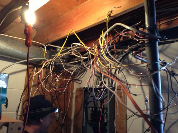
But then you guys show me things like this? Whats amatter with you!!! Have some respect for the arts! :cry:
Image
OK, I will focus on the 3d Scale plastic model this week and post some pics that maybe some of you would be willing to sketch over and suggest some electrical conduit pathways that are beautiful as well as functional... like biology! EXAMPLE: In the roof pattern one of the concepts I will prototype on a smaller scale goes like this:
Image
User avatar
GreenViking
Teardrop Advisor
 
Posts: 66
Images: 0
Joined: Tue Oct 06, 2009 4:08 pm
Location: AZ/CA
Top

Re: How to Future Proof access to your Wiring in a First Bui

Postby pchast » Wed Mar 04, 2015 9:33 pm

Ok back to basics.... Wiring elct101

all power must run in a circle(circuit)
All 12vDC power has a positive side and a negative side return in today's world.
all 120vAC power has a Hot (high volt) side and a Neutral (bonded) side

if one side of the circle is broken weird things can happen. Back feeding, Shock
potential, etc.

So the simplest solution is to use 2 wires to each and every appliance: light, power
outlet. etc.
Each supply(hot/high v) should be fused or circuit breaker supplied.
Each return (should be bonded together before returned to the Battery or AC power
supply.

Just think of everything in a circle and route circuits one at a time. Keep AC(alternating or
household current) Isolated from DC( direct or automobile common current)

That rats nest picture you saw is typical before things are straightened and neatly
tied(cleaned up)

Draw a line diagram of what appliances you wish to install before you start. Take some
time to dream of anything you may some time desire. Then talk to us again...

Luck<
pchast
Platinum Donating Member
 
Posts: 2066
Images: 97
Joined: Mon Jan 28, 2013 5:47 pm
Location: Athens, NY
Top

Re: How to Future Proof access to your Wiring in a First Bui

Postby MtnDon » Wed Mar 04, 2015 10:18 pm

pchast wrote:Ok back to basics.... Wiring elct101
............... and a Neutral (bonded) side
.........................

Each return (should be bonded together before returned to the Battery or AC power
supply.


Can you explain more fully what you mean by the word "bonded" .... ????
Our 6x12 deep vee nose cargo trailer camper conversion... viewtopic.php?f=42&t=58336

We have a small off grid cabin we built ourselves in the NM mountains; small PV solar system; 624 watts PV, Outback CC & inverter/charger ... http://countryplans.com/smf/index.php?topic=2335.0
User avatar
MtnDon
2000 Club
2000 Club
 
Posts: 2200
Images: 24
Joined: Sun Aug 19, 2012 10:57 pm
Location: New Mexico
Top

Re: How to Future Proof access to your Wiring in a First Bui

Postby pchast » Wed Mar 04, 2015 10:21 pm

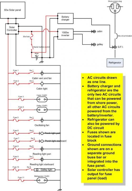
for an example I borrowed this schematic from Tiki TD at
viewtopic.php?f=30&t=37732&start=60
As you search through the forum you can find several others.

Your needs may vary.

Image
pchast
Platinum Donating Member
 
Posts: 2066
Images: 97
Joined: Mon Jan 28, 2013 5:47 pm
Location: Athens, NY
Top

Re: How to Future Proof access to your Wiring in a First Bui

Postby capnTelescope » Thu Mar 05, 2015 12:30 am

pchast wrote:I borrowed this schematic from Tiki TD ...

Oh, Pete. That is so Old School. :lol:

GreenViking wrote:I look at all those wires and then the artist/designer in me starts trying to make comparisons to this [cool picture]

This statement illustrates why, IMHO, as a general rule engineers make mediocre artists and vice versa. But wait, GV! Don't go away mad. You're on to something. Brandenberg's (BTW, is that you?) illustration of the nervous system is reminiscent of my New School schematic. For example: your index fingertip touches a hot surface. Pain sensors in the fingertip send an "Owie" alert through the nerves to the brain. The brain (controller) processes that information (software) and concludes there is a threat to the fingertip. Farther up that same arm are actuators (muscles). The brain sends actuation signals through different nerves to the muscles to get that finger off of the hot whatever-it-is and moves it in front of your mouth so you can blow on it. The software also sends a Speak:"Ouch!" command to the Verbal Output System. Or other utterances, ;) depending on the software version.

Let's think about Pete's schematic for a sec. If his black wires were colored blue instead, the schematic would be somewhat recognizable as a less artistic drawing of the circulatory system. Blood going out from the heart (battery), through the red arteries(wires), through some electrical organ(light bulb) and returning to the heart(battery) through the blue veins(wires). Same as an electrical circuit. To carry the analogy further, :dead: blood pressure is volts and the volume of flowing blood is amps.

GreenViking wrote: Have some respect for the arts!
Image

But
Tom wrote:Image


Here's where engineering collides with art. Or vice versa. To the engineer's eye, Tom's wiring panel is neat, tidy and organized. To the artist's eye, it is more like the first picture. Or at the very least, unartistic. Here's where your outside-of-the-boxedness has a chance to shine, GreenViking. The artistry of wiring has been focused on the functional rather than the beautiful. We hide it inside our walls or in conduits that march in formation. For the last hundred-odd years, the functional "beauty" of wiring has been judged by its being protected or organized or by not moving or changing color or making smoke, which are all considered functionally "bad."

So there's your challenge. But, like your nervous and circulatory systems, it does need to support some function. Aesthetically. Otherwise it is sculpture.
I'll burn that bridge when I come to it.

Brad
ImageImageImage

Building the Bed & Breakfast
User avatar
capnTelescope
Lifetime member
 
Posts: 1222
Images: 368
Joined: Sun Jun 27, 2004 3:44 pm
Location: Round Rock, TX
Top

Re: How to Future Proof access to your Wiring in a First Bui

Postby MtnDon » Thu Mar 05, 2015 12:33 am

pchast Sorry, but to me referencing that diagram doesn't do anything as far as clearing up the intent behind what was said about bonding.

First for those who don't have a clue what bonding is about; bonding is to connect an AC neutral to an AC ground. AC bonding should never be done in an RV.

Bonding is supposed to be done on the campground side, or if at home on the residential side and in one place only. That one place is normally in the main service panel. Sub panels do not have a bond. The RV electrical system is simply a sub system; any service panel in an RV is a sub panel. Having a bond in the RV as well as in the plugged into outside world, can cause an assortment of problems. Depending on what the RV is plugged into some of those can be dangerous, as in you can become the path to ground if there are incorrectly wired receptacles in the campground circuits.

I don't want to try and re-create an electrical text book here so I am going to leave this subject with a simple warning... do not insert a bond connection in any of the RV AC circuits. We want the RV to have an isolated or "floating" neutral.
Our 6x12 deep vee nose cargo trailer camper conversion... viewtopic.php?f=42&t=58336

We have a small off grid cabin we built ourselves in the NM mountains; small PV solar system; 624 watts PV, Outback CC & inverter/charger ... http://countryplans.com/smf/index.php?topic=2335.0
User avatar
MtnDon
2000 Club
2000 Club
 
Posts: 2200
Images: 24
Joined: Sun Aug 19, 2012 10:57 pm
Location: New Mexico
Top

Re: How to Future Proof access to your Wiring in a First Bui

Postby GreenViking » Thu Mar 05, 2015 7:05 pm

Thank you Pete for the rules of thumb basic version. As I get to the place of taking the 3D model around I will get plenty of suggestions and wishlists that will inform the electrical needs both basic and pie in the sky!!

I am methodically taking notes on ALL the suggestions I am getting here :thinking: . I am leaving lots of room/hackability for future possibilities/uses in the area of what micro trailers as a platform can become the base for, and particularly in the area of serving the needs beyond camping rural areas.
So yes, agreed, my efforts will be put first on the physical scale model. That will give a wonderful place to focus the discussion on both the needs AND finding a functional AND inspiring form that is there to Shepard great experiences for both those that use the FireBeetle and those that witness it's use.

Brad, so thank you very much for your comparison and expressing some understanding to the need for a metaphor that is digestible to more of a designers leaning (not artists necessarily, the difference for those interested can be found here: http://www.hongkiat.com/blog/design-vs-art/)

Tom, Thank you so very much for the detailed pics and I appreciate your documenting the process you took to get there! :applause: It does provide much insight!
User avatar
GreenViking
Teardrop Advisor
 
Posts: 66
Images: 0
Joined: Tue Oct 06, 2009 4:08 pm
Location: AZ/CA
Top

Re: How to Future Proof access to your Wiring in a First Bui

Postby pchast » Thu Mar 05, 2015 9:40 pm

MtDon

Bonded was a bad word choice...
Better stated: use a terminal strip to collect all the returns.
:thinking:
I was not referring to AC, household style wiring.
My background was as a Heating Plant Engineer not an Electrician.
:)
pchast
Platinum Donating Member
 
Posts: 2066
Images: 97
Joined: Mon Jan 28, 2013 5:47 pm
Location: Athens, NY
Top

Re: How to Future Proof access to your Wiring in a First Bui

Postby MtnDon » Thu Mar 05, 2015 10:32 pm

pchast wrote:Better stated: use a terminal strip to collect all the returns.


:thumbsup:
One terminal strip for the neutrals and one for the grounds; called a buss bar. Sort of a mirror image of the hot wire terminals but without the breakers / fuses.
Last edited by MtnDon on Fri Mar 06, 2015 9:54 pm, edited 1 time in total.
Our 6x12 deep vee nose cargo trailer camper conversion... viewtopic.php?f=42&t=58336

We have a small off grid cabin we built ourselves in the NM mountains; small PV solar system; 624 watts PV, Outback CC & inverter/charger ... http://countryplans.com/smf/index.php?topic=2335.0
User avatar
MtnDon
2000 Club
2000 Club
 
Posts: 2200
Images: 24
Joined: Sun Aug 19, 2012 10:57 pm
Location: New Mexico
Top

Next

Return to Electrical Secrets

Who is online

Users browsing this forum: No registered users and 0 guests