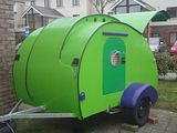
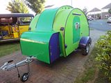
16 foot single wheel unusual TD build

...ask your questions in the appropriate forums BUT document your build here...preferably in a single thread...dates for updates, are appreciated....

Re: 16 foot single wheel unusual TD build

Postby 3nero » Tue May 13, 2014 7:16 pm

No worries.
Just a couple more tips while i think of them. You need to heat a wider strip to make the plastic follow the curve of the pole, try zig zaging the gun up and down as you move side to side. the bend need to start at the the 12 o clock position on the pole you used and finish at the 9 o clock position to get the same radius. If you are building a former or jig to bend on remember to minus the thickness of your sheet to get the right size radius on any bends. I.E. a 10mm outer radius in a 3mm thick piece will need a 7mm radius in the former.
Measure once, cut twice....throw away and repeat.
Image Image

http://www.tnttt.com/viewtopic.php?t=55971
3nero
Teardrop Master
 
Posts: 129
Joined: Mon May 13, 2013 3:40 pm
Location: Co.Wicklow Ireland

Re: 16 foot single wheel unusual TD build

Postby WeirdDogGuy » Tue May 13, 2014 8:25 pm

Zig zag, yes, great ideas here. Thx again.Andy
User avatar
WeirdDogGuy
Teardrop Advisor
 
Posts: 79
Images: 13
Joined: Tue Apr 15, 2014 5:21 pm

Re: 16 foot single wheel unusual TD build

Postby WeirdDogGuy » Sun May 18, 2014 3:48 pm

For my third bend experiment, I used a 2 inch DIA piece of well casing for the mandrel. The OD of the pipe is 2-1/4 inch. I filled it with a bunch of nuts and bolts to increase the mass, then I cooked it in the oven at 250F for a half hour. This may not be necessary but I'm paranoid about burning or bubbling my plexi. A nice thing about using a heated mandrel is that you know what the heat is. You are just guessing when you use a heat gun and if you stall in one spot too long or get too close to the work, you risk bubbling the plexi. So, I heated the mandrel and since that provided heat from below, I could use less heat from the gun and reduce the risk of bubbling. I used more of a zig zag motion over the bend area and I did get the radius that I want-just over an inch. This is probably pretty close to the bend that I'll be using in my wrap-around corner windows.

avll24.jpg
avll24.jpg (75.86 KiB) Viewed 1555 times
User avatar
WeirdDogGuy
Teardrop Advisor
 
Posts: 79
Images: 13
Joined: Tue Apr 15, 2014 5:21 pm
Top

Re: 16 foot single wheel unusual TD build

Postby WeirdDogGuy » Wed May 21, 2014 9:22 pm

Back to metalworking. I was test fitting my hinge bracket tonight and I unscrewed the hinge pin bolt. Wow. It just slid out of the assembly no problem. This is good news because now I have the option of unbolting the hinge bracket from the other side of the car (the other half of the axle that I cut) and using it. I will just need to buy a longer metric bolt that will pass through both brackets and the sleeve on the swing arm.

avll25.jpg
avll25.jpg (62.93 KiB) Viewed 1514 times
User avatar
WeirdDogGuy
Teardrop Advisor
 
Posts: 79
Images: 13
Joined: Tue Apr 15, 2014 5:21 pm
Top

Re: 16 foot single wheel unusual TD build

Postby WeirdDogGuy » Sun May 25, 2014 9:44 pm

I removed the hinge bracket from the other side of the axle and used it to complete my new swing arm hinge. The original bolt was 12mm and since it was originally designed to go through one hinge bracket and the swing arm sleeve, it was too short. I live in a podunk town and no way I'm going to find a long 12mm bolt. I could have ordered one but I'm in a hurry to get going on this and I didn't want to wait. Since 1/2 inch is pretty close to 12mm (.5IN=12.7mm), I just drilled out the washers and sleeves that where on the original axle. The sleeve on the swing arm had enough slop in it so I didn't need to drill it. I had to drill the big washers and the steel sleeve that passes through the big rubber bushing. It went pretty fast since I didn't have to remove much metal-more of a ream job really. Now that all my opennings were enlarged to 1/2 IN, it was a simple matter to go to the hardware store and buy a longer hinge pin bolt. The closest size length that they had in stock was 9 inches and that's what I used. Here's a bad pix of the finished assembly. I'm losing daylight so it's not very good and if I find the time tomorrow, I'll get a better one:

avll26.jpg
avll26.jpg (31.68 KiB) Viewed 1463 times


On top of my new hinge assembly in the pix is the old 12mm bolt. You can see how it's too short for the new assembly. That's the latest....
User avatar
WeirdDogGuy
Teardrop Advisor
 
Posts: 79
Images: 13
Joined: Tue Apr 15, 2014 5:21 pm
Top

Re: 16 foot single wheel unusual TD build

Postby angib » Mon May 26, 2014 8:17 am

That wheel is going to be free to flop about, isn't it? Two brackets spaced a few inches apart, with rubber inside them, aren't going to keep the wheel pointing straight ahead. Previously those brackets were several feet apart.

Assemble it all and bolt it to something rigid (doesn't have to be the frame) and see how easy it now is to move the wheel sideways.
User avatar
angib
5000 Club
5000 Club
 
Posts: 5783
Images: 231
Joined: Fri Apr 30, 2004 2:04 pm
Location: (Olde) England
Top

Re: 16 foot single wheel unusual TD build

Postby KCStudly » Mon May 26, 2014 11:34 am

... or to twist it so the tire contact patch is tilted.

It is likely that you can buy aftermarket polyurethane bushings that fit that application, or maybe even solid aluminum (for racing applications). If not you could make some solid bushings to take out any undesirable play.
KC
My Build: The Poet Creek Express Hybrid Foamie

Poet Creek Or Bust
Engineering the TLAR way - "That Looks About Right"
TnTTT ORIGINAL 200A LANTERN CLUB = "The 200A Gang"
Green Lantern Corpsmen
User avatar
KCStudly
Donating Member
 
Posts: 9640
Images: 8169
Joined: Mon Feb 06, 2012 10:18 pm
Location: Southeastern CT, USA
Top

Re: 16 foot single wheel unusual TD build

Postby KCStudly » Mon May 26, 2014 11:37 am

Another thing you may want to consider is building in some adjustment to the mounting provisions, either cam bolts or shims (like nearly all automotive suspensions) that will allow you to adjust the alignment once installed (both toe and camber).
KC
My Build: The Poet Creek Express Hybrid Foamie

Poet Creek Or Bust
Engineering the TLAR way - "That Looks About Right"
TnTTT ORIGINAL 200A LANTERN CLUB = "The 200A Gang"
Green Lantern Corpsmen
User avatar
KCStudly
Donating Member
 
Posts: 9640
Images: 8169
Joined: Mon Feb 06, 2012 10:18 pm
Location: Southeastern CT, USA
Top

Re: 16 foot single wheel unusual TD build

Postby WeirdDogGuy » Mon May 26, 2014 12:24 pm

angib wrote:That wheel is going to be free to flop about, isn't it? Two brackets spaced a few inches apart, with rubber inside them, aren't going to keep the wheel pointing straight ahead. Previously those brackets were several feet apart.

Assemble it all and bolt it to something rigid (doesn't have to be the frame) and see how easy it now is to move the wheel sideways.


Here is a better pix of the assembly:

avll27.jpg
avll27.jpg (138.43 KiB) Viewed 1424 times


The only thing that you can't see in the assembly is the steel sleeve bushings inside the rubber sleeve. This is what they look like:

vw.JPG
vw.JPG (78.56 KiB) Viewed 1424 times


When I increased the bore to accommodate the larger 1/2 IN hinge pin, all the holes that I reamed had a snug fit. The largest clearance in the system was the metal pass-through sleeve that is welded to the swing arm. I didn't have to ream it since there was enough clearance to accommodate the larger 1/2IN bolt. So by using a slightly larger bolt, I've actually reduced freeplay by chance. Futhermore, as the nut is tightened, everything goes into compression (except bolt of course) and the rubber bushings have a shoulder that keeps everything nice and snug. If I tighten the nut too tight, the assembly will not rotate in the swing arm sleeve without a lot of force to overcome the friction that the rubber shoulder on the bushing is applying. This is a very clever system and that's why the engineers at VW used it. I'll probably experiment with nut torque to get a snug fit on everything, sort of a Goldilocks setting, then drill the bolt and pin a castlenut on so I don't have to worry about the nut vibrating off. I can feel no movement on the bench and I'm confident there will be no unacceptable slop when it's mounted. But of course, I'll check. Thanks for your comments. This helps me rethink the system and makes me sure that I didn't miss anything. Andy
User avatar
WeirdDogGuy
Teardrop Advisor
 
Posts: 79
Images: 13
Joined: Tue Apr 15, 2014 5:21 pm
Top

Re: 16 foot single wheel unusual TD build

Postby WeirdDogGuy » Mon May 26, 2014 12:35 pm

KCStudly wrote:Another thing you may want to consider is building in some adjustment to the mounting provisions, either cam bolts or shims (like nearly all automotive suspensions) that will allow you to adjust the alignment once installed (both toe and camber).


I thought about doing this but really, I just think it's overkill. Maybe I'm wrong, we'll see, but I'm going with the simplicity of a direct mounting. I have the option of slotting the holes in the mounting brackets, or using mounting bolts that are smaller than the holes. That would give me a degree or two of adjustment. If I'm careful about the alignment when I layout the hole location, I think I'll be OK. The only thing left to do before mounting is to trim the end of the swing arm. Since it ends passed the hinge point, it's pretty close to the frame when mounted and can theoretically bottom out on the frame.

Thx for your comments.Andy
User avatar
WeirdDogGuy
Teardrop Advisor
 
Posts: 79
Images: 13
Joined: Tue Apr 15, 2014 5:21 pm
Top

Re: 16 foot single wheel unusual TD build

Postby WeirdDogGuy » Wed Jun 04, 2014 7:19 pm

I'm preparing to bolt my hinge brackets to the frame. When I first drew this design in autoCAD, I drew it with the VW wheel attached to the swing arm because at the time, I had not machined the hub to accept a Soob wheel. I want to use a Soob wheel for the trailer since I won't need to carry another spare. The car spare and the trailer spare will be the same. I clamped the swing arm in place on the frame and I mistakenly left the vw wheel on the swing arm. Here's what it looked like:

avll28.jpg
avll28.jpg (116.72 KiB) Viewed 1379 times


avll29.jpg
avll29.jpg (85.25 KiB) Viewed 1379 times


But then I realized that I had the wrong wheel on and I swapped the wheel to the Subaru without changing the bracket spacing. Here's what it looks like with the Soob wheel mounted:

avll30.jpg
avll30.jpg (79.02 KiB) Viewed 1379 times


I was surprised that they aligned pretty much the same. I don't know if this is a coincidence or if it's some sort of industry standard that the center line of the tire track is the same regardless of rim design (depth of dish, etc,etc).
User avatar
WeirdDogGuy
Teardrop Advisor
 
Posts: 79
Images: 13
Joined: Tue Apr 15, 2014 5:21 pm
Top

Re: 16 foot single wheel unusual TD build

Postby WeirdDogGuy » Sat Jun 14, 2014 11:58 pm

The air bags that I ordered have a 1/2 IN DIA NPT fill port. I used a standard air valve stem that is meant to fit a .453 hole in an auto rim for my fill port. Usually, when I make these, I just drill a .453 DIA hole in a pipe cap and pull the valve stem through it with a valve stem tool. But I had a stainless steel nut in my plumbing bucket of odds n ends. It's the nut that connects the riser from the water supply to a sink. They have a 1/2 IN hole in them to accommodate the riser supply. I wasn't sure if it would work since the .5 IN hole in the supply nut is larger than the .453 hole that the air valve stem is designed for in a standard car rim. When I pulled the air stem through the hole, the bottom end of the stem filled the inside of the nut. When I screwed a 1/2 IN PVC nipple onto the nut, it compressed the end of the stem further into the nut making a nice and tight seal. I put a pipe cap on the other end of the nipple and pressure tested it and it held pressure fine. It will be easy to access this nipple and change the pressure from an air source - compressor, bike pump, etc,etc. My swing arm is hollow and if I weld end caps on it, I could use it to store compressed air -so the swing arm would also be an air tank. It would not be a very big tank since the swing arm isn't very big so I haven't decided if it's worth doing or not.
Attachments
avll31.jpg
avll31.jpg (25.7 KiB) Viewed 1296 times
User avatar
WeirdDogGuy
Teardrop Advisor
 
Posts: 79
Images: 13
Joined: Tue Apr 15, 2014 5:21 pm
Top

Re: 16 foot single wheel unusual TD build

Postby WeirdDogGuy » Tue Jun 17, 2014 10:38 pm

Laying out the perch for my airbag.

avll32.jpg
avll32.jpg (98.19 KiB) Viewed 1241 times
User avatar
WeirdDogGuy
Teardrop Advisor
 
Posts: 79
Images: 13
Joined: Tue Apr 15, 2014 5:21 pm
Top

Re: 16 foot single wheel unusual TD build

Postby WeirdDogGuy » Thu Jun 19, 2014 10:36 am

Checking for fit, top perch:

avll33.jpg
avll33.jpg (88.69 KiB) Viewed 1199 times
User avatar
WeirdDogGuy
Teardrop Advisor
 
Posts: 79
Images: 13
Joined: Tue Apr 15, 2014 5:21 pm
Top

Re: 16 foot single wheel unusual TD build

Postby WeirdDogGuy » Mon Jun 30, 2014 10:33 pm

The bottom bag perch is just a piece of angle iron with a hole drilled through it for the 3/8s IN anchor bolt that is tapped into the bottom of the air bag. When I cut the swing arm, I left a bit of the iron angle brace attached to the arm so it would give me something to weld the perch to; you can see the stub in the pix;

avll34.jpg
avll34.jpg (88.19 KiB) Viewed 1088 times


Eyeballing clearances. If I ever have a blowout, the shredded tire may take out my airbag since there's only about an inch clearance between the two so I may put in a shield to protect the airbag.

avll35.jpg
avll35.jpg (83.41 KiB) Viewed 1088 times
User avatar
WeirdDogGuy
Teardrop Advisor
 
Posts: 79
Images: 13
Joined: Tue Apr 15, 2014 5:21 pm
Top

PreviousNext

Return to Build Journals

Who is online

Users browsing this forum: No registered users and 2 guests