Randy, I wish I had known about the tractor swap sooner. I would have gladly looked for your needed fuel separator. I bet I could have found one, too. That is exactly the type of thing that shows up there by the bin full! Post a good picture of what you need and I will look again next year.
I’ve been working along and loading pictures up (lots of them), but have fallen behind on updates. Let’s get caught up, shall we?
After scoring some tools and white gas appliances at the swap meet (
detailed thread here) I spent the rest of Saturday working on the locker door assembly.
Here is the door after gluing one rail, removing clamps, removing tape and scraping the glue joints.
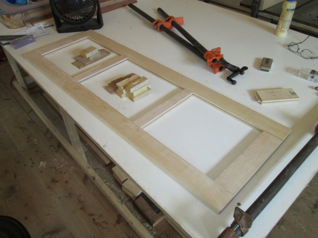
Oh happy, happy joint.
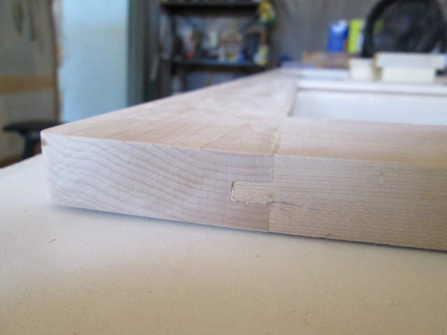
By fitting the loose rail, shimming the assembly up off of the pipe clamps, and clamping it up with the toes of the clamps below the face of the frame I was able to run the router around the inside edges of the panel openings using the 1/8 inch round over bit; two operations, inside face and out.
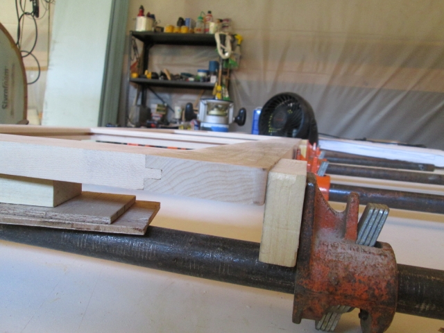
With a lot of handwork and a scrap of 220 grit wrapped around a small stick, I was able to dress up the corners where the router couldn’t reach.
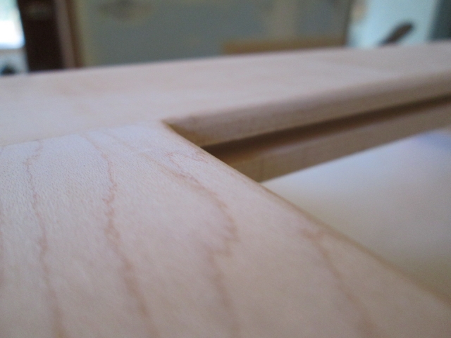
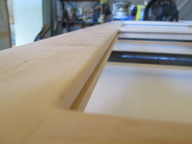
The “front” outside edge of the face got 1/4 inch round over. Took a couple of different clamp ups to do the edge at the joint, then move the bar clamps out of the way to get the rest.
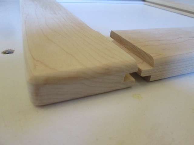
Here you can see how I blended the inside corners of the mullions while clamped, prior to installing the panels and having them be in the way (shown separated after unclamping).
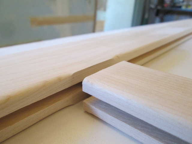
The outside edge on the “back” face of the frame where it closes against the wall got the 1/8 inch round over to ease the edge and prevent head knockers. Here you can see the profile inside and out, front and back.
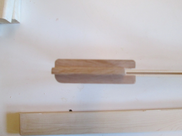
Another dry fit. I’m really happy with the way this is turning out!
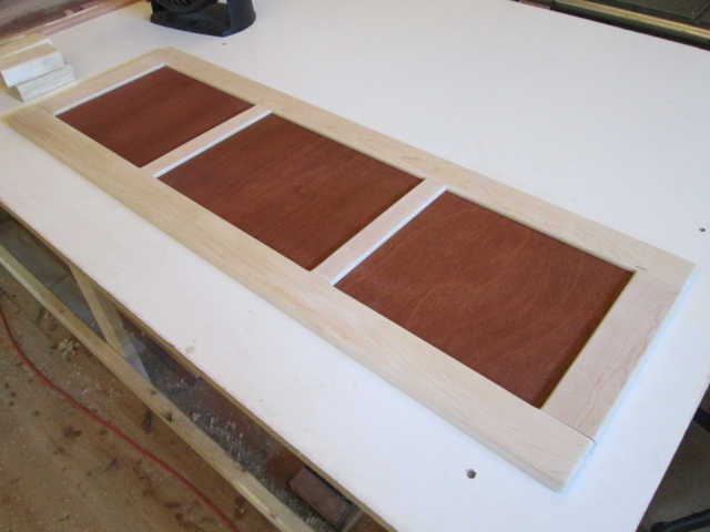
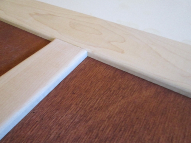
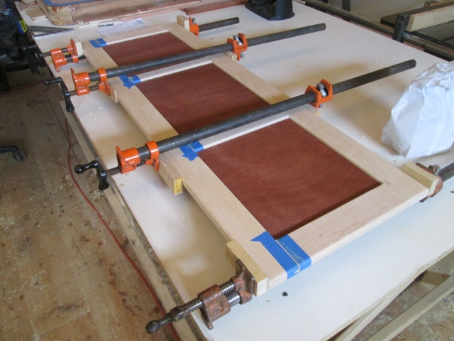
Finished up the day by masking and gluing up the second rail with the panels installed. So that was about 5 hrs at the swap and another 7 hrs fussing with details.
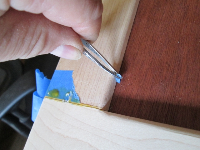
Sunday I put in another 6 hrs dressing the glue up and working on fitting the door hardware. Here is one of the glue joints “fresh out of the mold”.
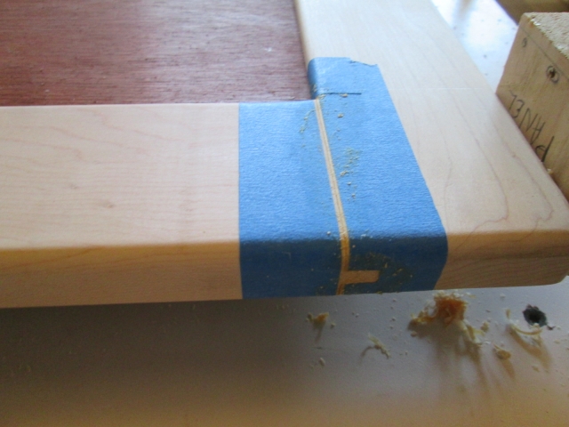
The tweezers I got at the swap meet have already been put to use!
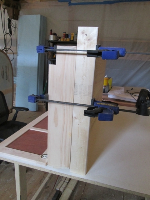
To fit the door to the locker hinges I had to prop the locker upside down on the bench. Because the slanted top wouldn’t let it stand on its own, I clamped a piece of 2x3 on the front to act as a foot.
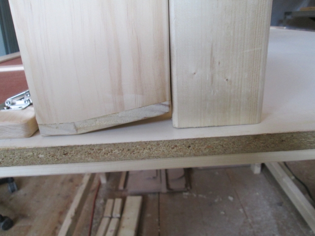
Because the hinges are articulated to swing the door out, then back down the instructions call for a 3.5mm gap so that the corner of the door does not hit. Rather than use the paper template supplied, I used a couple of shims that matched the template; one seen here.
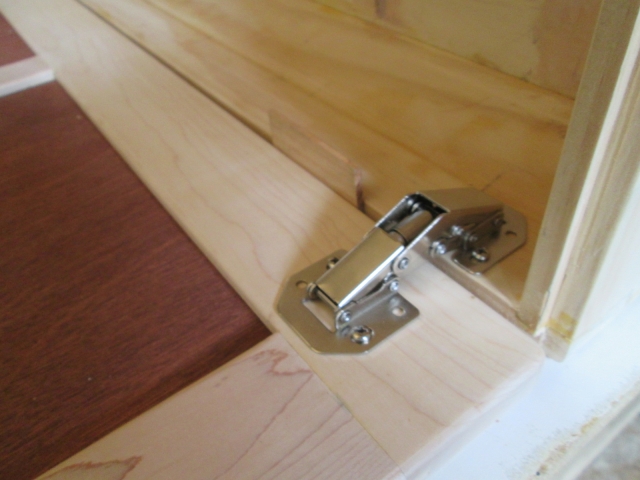
Still upside down, here it is with the door closed.
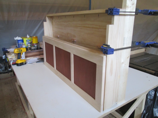
You can see how the hinge holds the panel out a little at the top (bottom of pic), but no bother.
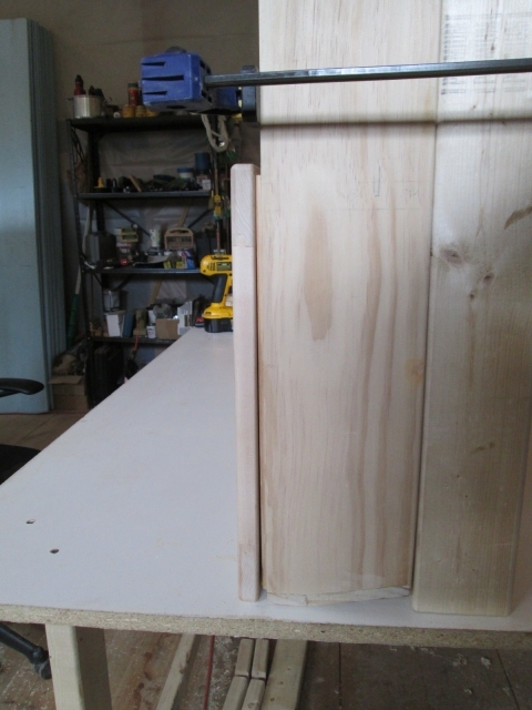
Here it is upright.
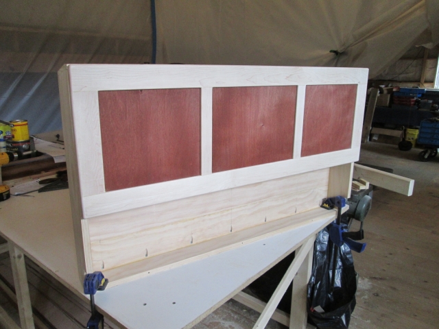
The springs in the hinges weren’t sufficient enough to hold the door up, so the stick is just there for the photo op.
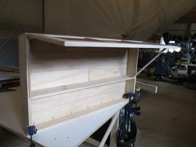
Even if I added a couple more hinges of this type, I don’t think it would be enough, and if I put more in the middle of the cabinet I think that would start to block access more than I want. I’m shopping for some folding props; something simple. Any suggestions?
Next up I wanted to do a test run on mounting the cam style lock cylinder, and making a slot for the striker. The lock is sized for 9/16 maximum thickness, so I would need to recess the double-D anti rotation washer and gland nut in the back side of my 3/4 inch thick frame rail. Using the milling machine, I bored the required 3/4 inch diameter hole for the barrel of the lock using a Forstner bit, then on the same center (concentric) I used the 1-1/4 slugger to counter bore the washer recess.
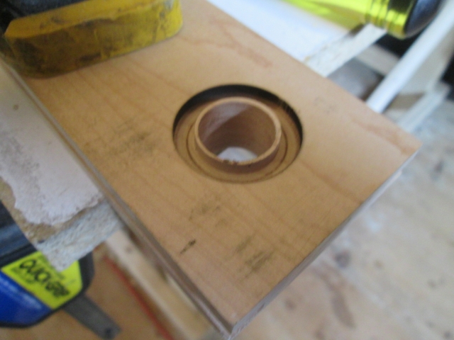
That left a small lip that needed to be chiseled out.
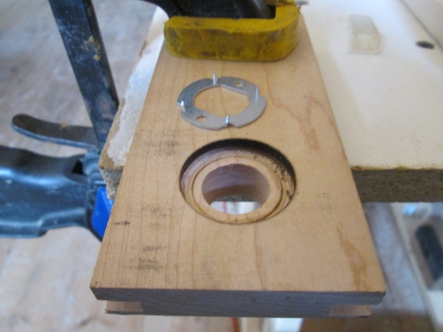
You can also see the double-D washer with little spiky cleats that will get pressed into the recess (I left it out for now).
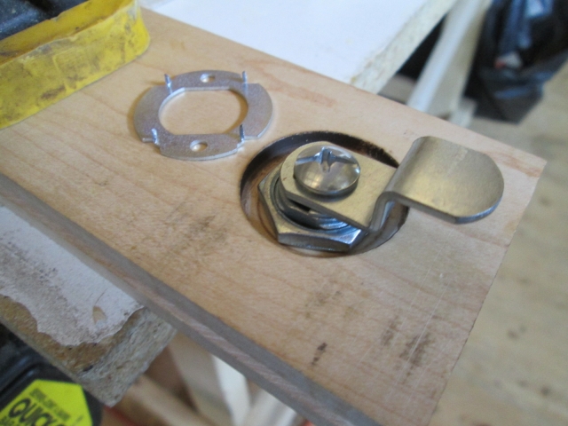
The “front” side of the lock mockup.
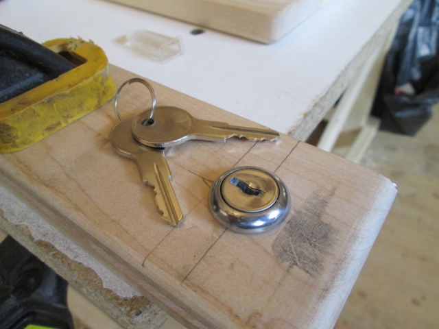
I wasn’t sure if I would be able to chisel out a decent slot for the cam, so I cut another scrap of pine to simulate the divider sill in the locker and gave it a go. Because of the depth of the 1/4 inch wide slot required, that I couldn’t get the tip of the utility knife down in the hole far enough to cut the ends of the grains, and the fact that I don’t have a 1/4 inch wide chisel, I made one out of a piece of bar stock.
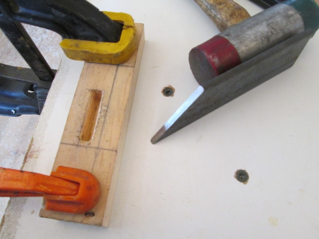
Harvested from Karl’s scrap bin, this piece of 1/8 thick SS strip will get milled into a slotted striker plate and will be recessed into the sill with a couple of flat head SS screws (shown long and off to the front side).
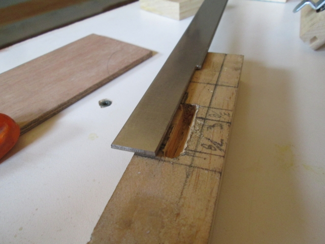
I had some issues with the slot (see more below). In hindsight, I will have a “do over”. I think I can fit the plunge router into the locker opening and use the 1/4 inch straight cutter to make a cleaner slot.
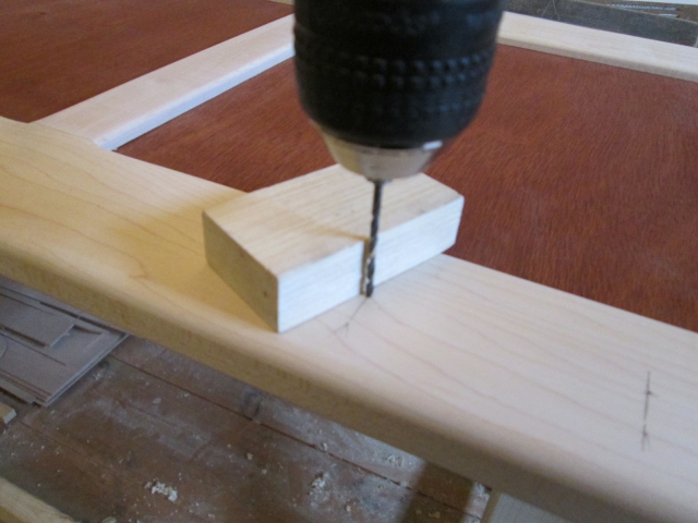
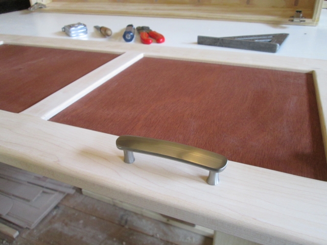
I was very careful laying out for the handle placement. I really wanted the handles to look centered on the outside panels, and on the height of the bottom rail, and I didn’t want them to look crooked. Careful measuring and marking with a quick square, then pricking the center mark with the tip of a deck screw helped get the pilot drill started exactly where I wanted it.
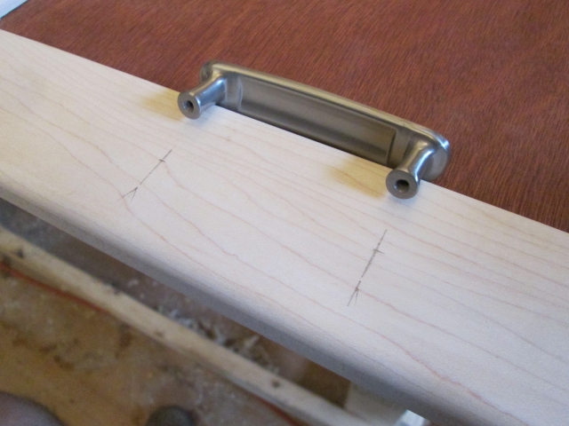
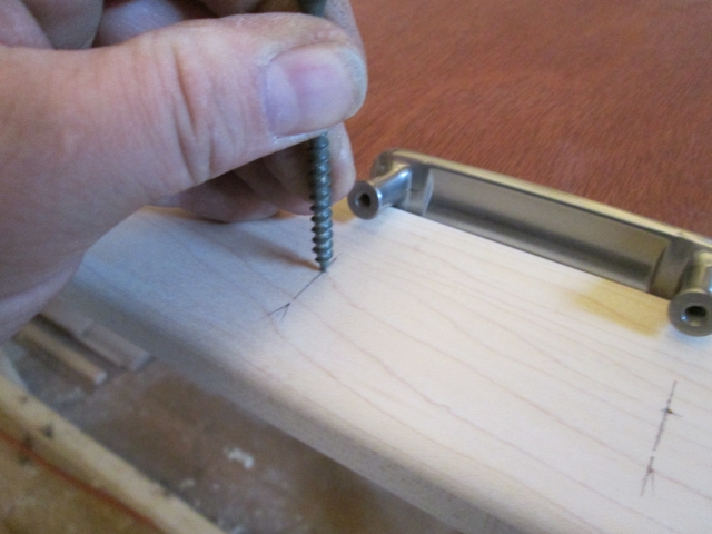
I used a small block as a guide, checking two axes to plumb the pilot drill bit before drilling up for the 8-32 screws.
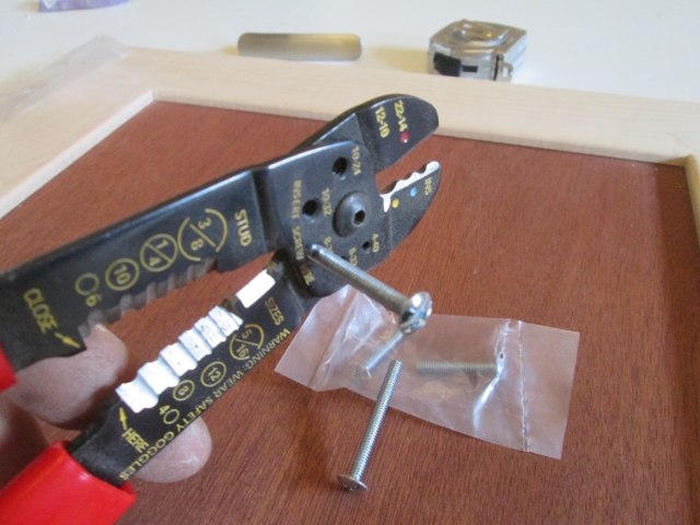
There were two different length screws that came with the pulls. The shorter ones only stuck out about 1/4 inch, but if I cut the longer ones down I could get 3/8 inch engagement. I can be a little heavy handed sometimes so I hedged my bet on stripping out the threads by cutting down the longer screws. Used the small thread shearing feature on my wire strippers.
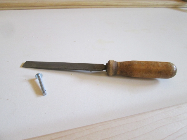
Just to be sure, and maybe to justify the purchase, I used the newly acquired fine file to remove the burrs and chamfer the lead threads to make sure that they didn’t wipe out the female threads in the pulls.
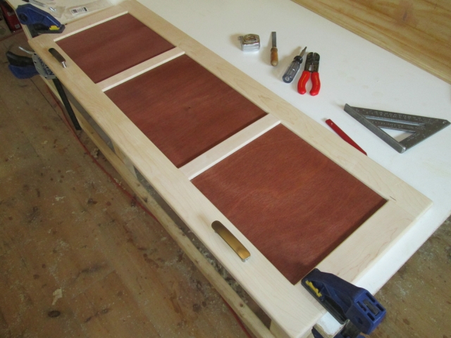
Prefitting the hand pulls worked out well.
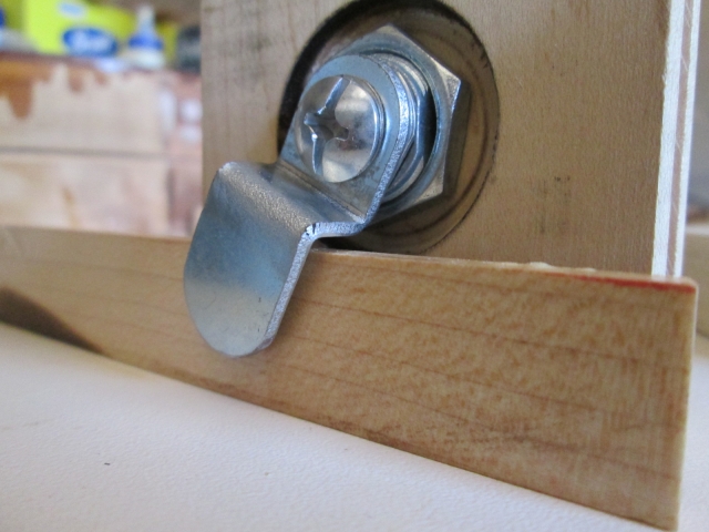
Getting back to the cam lock striker slot. With the tumbler centered where I wanted it the zig in the cam’s offset would clear at rest, but when swinging thru its arc the sides of the zig would hit the sill. Covered up by the striker stock shown in the picture up above, was another divot that I chiseled out trying to get it to swing. I didn’t like that, and at first I thought I would just raise the tumbler up about 1/4 inch, but that didn’t sit well with me either. So after mulling it over while I worked on these other things I struck upon a better solution. The lock set comes with three different cams: a short flat, a short offset (or “zig-zag”), and a long flat. By bending the long flat cam closer to the screw hole using a combination of Karl’s sheet metal brake (for the first bend) and a vice with a makeshift punch for the second bend, I was able to provide extra clearance for the cam to swing.
Here is the difference in offsets.
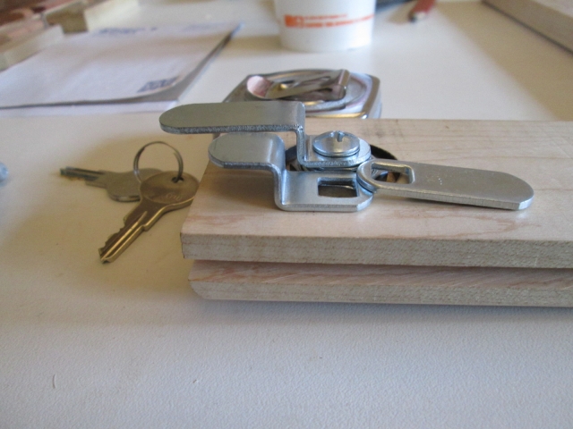
Here it is after trimming to length and rounding over on the Bader (belt sander).
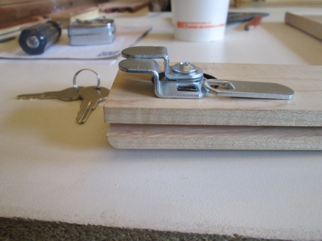
And here is a mockup sequence showing how the cam can now swing without hitting the sill. Note how there is less clearance part way thru the swing.
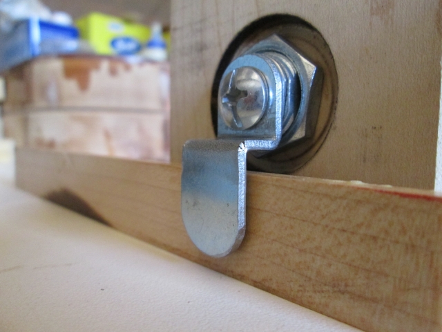
On the way home I stopped at The Orange and got some short #6x1/2 SS flat head screws for the striker plate, and some bright zinc plated ones to use screwing the front wall skin to the cabinet ledgers.
So now it is Monday. I’m still at work (though off the clock). I have a couple of wrought railing end caps to blast for Karl and am going to see if I can get the striker plate milled out.
All for now.


 . Also, after zipping the miter back and forth many times nibbling away at the tenons, I started to notice that the boards weren’t running perpendicular to the stop any more.


 Randy
Randy
