Thanks for looking, Dave.
Okay, so this post is going to be a little off topic, but in a horse trading sort of way this is work going toward my build.
Forgive me if I get some details wrong. I will try to relate what I heard or over heard about the Land Rover resto-mod project.
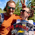
The chassis and running gear dates from somewhere in the mid to late 1990's. The mostly aluminum body is a collection from something like 6 or 8 different vehicles from the late 1960's to early 1970's, except the doors are newer and have roll-up windows instead of half sliders.
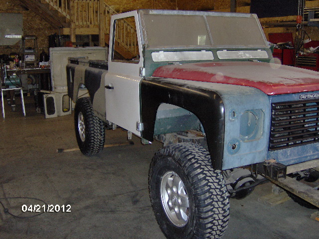
Here we have the frame lifted up on the saw horses and leveled side to side.
This was a group project. Mike, the guy with the cabinet shop/high end contracting business and CNC router, his son, and a couple of other young men brought this out with the body just sitting loosely on the frame. Our job was to help align it, and build and install all of the body mounts. Later, the chassis will be stripped down and sent out for hot dip galvanizing.
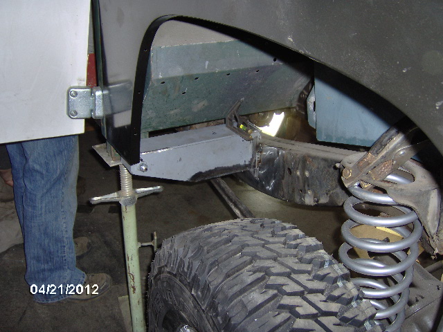
The outriggers that support the door post/fire wall/cowl assembly were already notched to clear the front suspension links at full droop. I cut, formed and welded the boxing plates to fill the notched sections.
And here is one of the outriggers in place as seen through the front wheel well.
Here are the crusty old formed channel door sills.
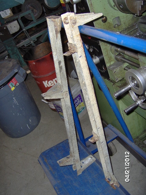
The extra bits in the middle were for a short piece of sheet metal trim that will be eliminated in order to fit rock sliders.
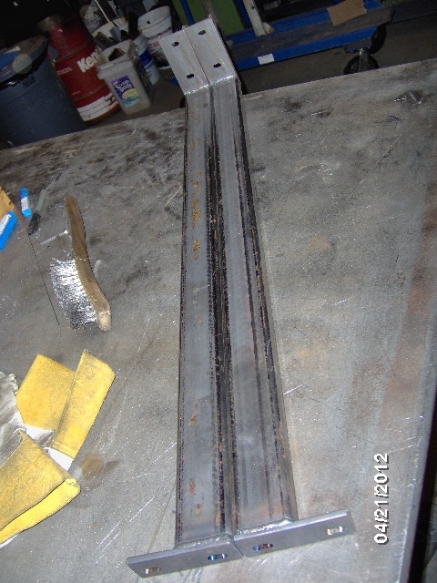
And here are the new tubular ones that Karl fit and I welded.
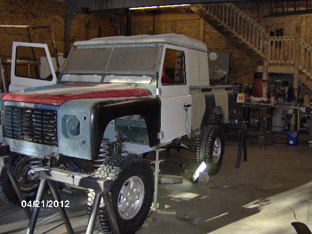
Here's a pic with the shortened roof cap on. If you look closely you can see the seam where Karl had previously welded the sectioned cap back together. Not as visible is the sharpie outline where the rear side windows will be cut in. There will be side facing jump seats in the back of the cab accessible through the original rear hatch.
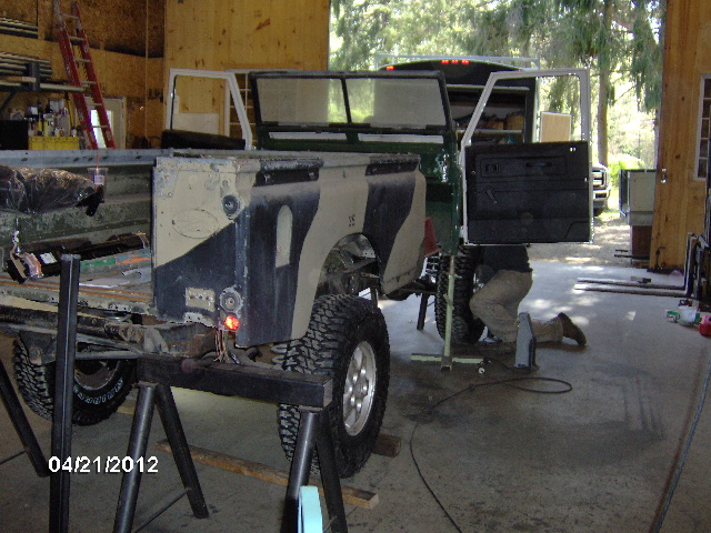
This piece, and the opposite hand version behind it, is another outrigger that I built to span from the top of the frame to under the door sill, supporting the front of the seat pan, the rear of the front floor sheet metal, and the future rock slider/running board. The kick up notch on the inboard side is to clear the rubber mount on the frame end of the trans xmbr. The notch platform with plate ledge is where the door sill will bolt on, and the pied wedge on the bottom right matches the height of the rock slider rail.
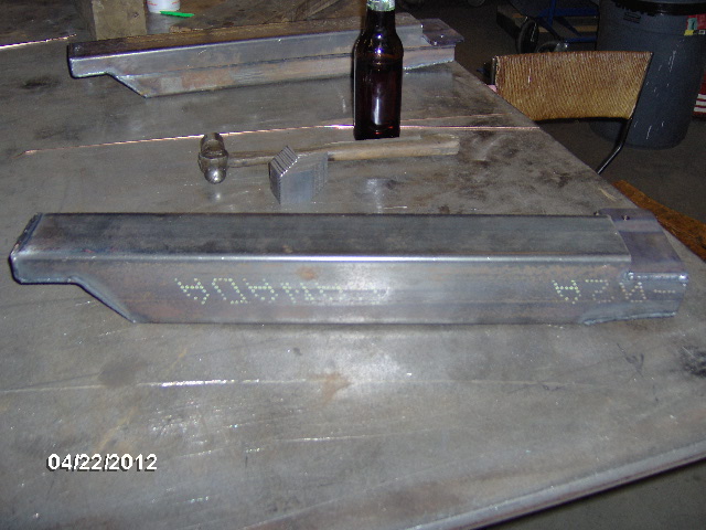
Here's the door sill end. It will get another bolt hole down thru the box with a pipe sleeve so that there is access to the nut from the bottom.
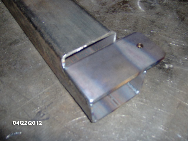
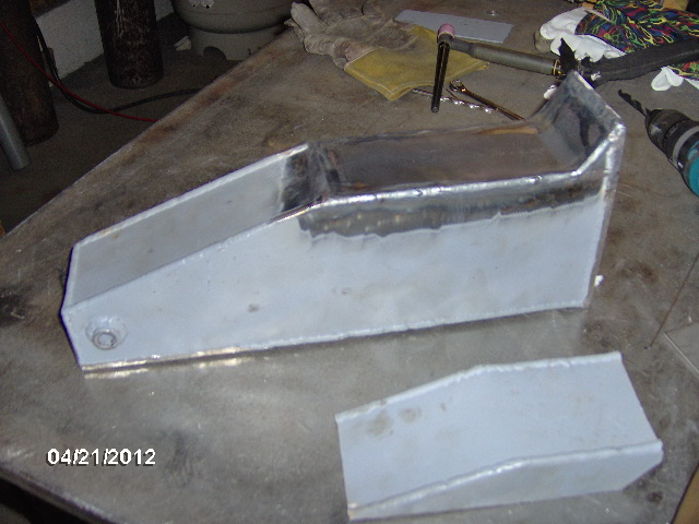
And here's a close up shot with it upside down showing the pie section wedge shape, and tab weld in detail.

Next weekend we will finish fitting and installing these. In the mean time, Karl and one of the guy's finished building the bed support rails, added braces to the fire wall in the foot well area, bobbed the rear of the frame to accept the cut down stock bumper assembly (which is also the rear bed mount), and welded some temporary braces so that we could take it off of the horses and free the shop back up for the work week.


 I also have a terrible case of frame envy. Man you do gorgeous work!


 and many pieces that need to be cut, milled, fit, glued, etc. etc. in some form or another. Lots of pieces to touch.


 That doesn’t sound right ...