Yeah Randy, even the simplest plans seam to become complicated.
Today wasn’t so bad at work but I had to read a boring document and it nearly put me to sleep. The only funny (ironic?) thing was the reference to a Standard Operating Procedure, “SOP 602 Procedure for Writing Standard Operating Procedures”. The ironic thing is that it was not SOP 001. So by the end of the day, after the bell I was literally falling asleep.
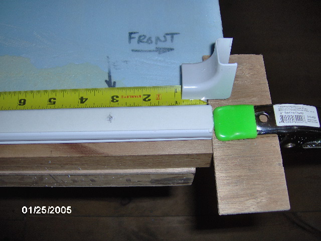
Okay, this pic gets kind of complicated. The lighter color curved piece in the center (with the notes written on it telling me that I used it as a wire channel template and how far away from the door jamb that was) is the same scrap router template as before, just repositioned to pass through the center of the pillow light/reading light location with the wire channel running aft a bit before turning down into the sill. The curvy bit clamped on the right was just a convenient way of making a stop for the router that could extend down past the end of the guide template. The piece above and the curvy bit to the left are just scraps laid there to shim the “free” side of the router shoe so that I didn’t have to try too hard to keep it level (they are just lying there, not even taped or screwed).
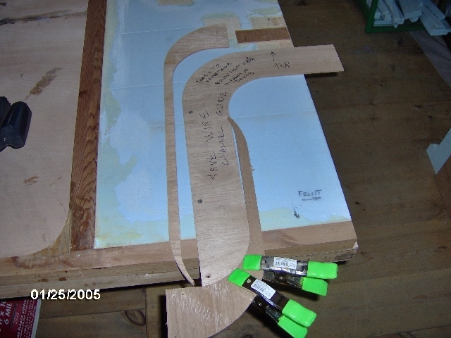
The resulting wire way channel will allow me to make a mounting block for the pillow light and switch that screws to the recess block, supports the side of the key catcher shelf, raises the switch adequately, and provides an opportunity to angle the light fixture in 3 dimensions to aid in aiming it.
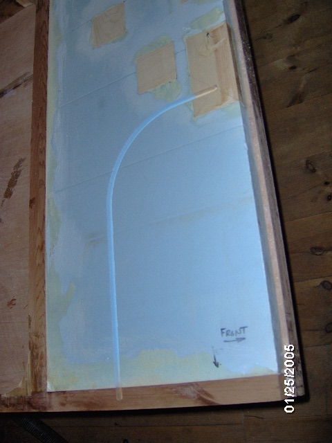
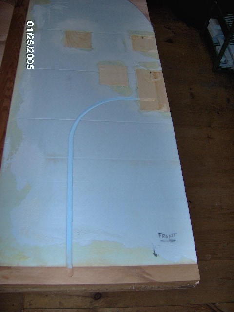
Also, the arc makes pulling wires easier and places the stress point created by the cut in the sill away from the front corner and away from the door jamb. Once the skin is on it won’t be much of a stress point, but it is still a consideration in my mental (insert joke here) process.
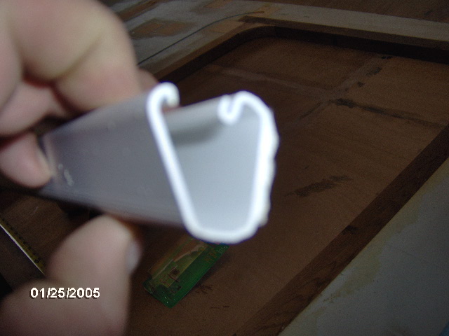
Here is a closer, albeit blurry look at the Wiremold PVC track. There is a seam where the catch lip seats which I might orient down for decorative purposes, but since the whole thing will be hidden by the mattress I will put the opening side up for easier access and gravity assist in laying wires inside.
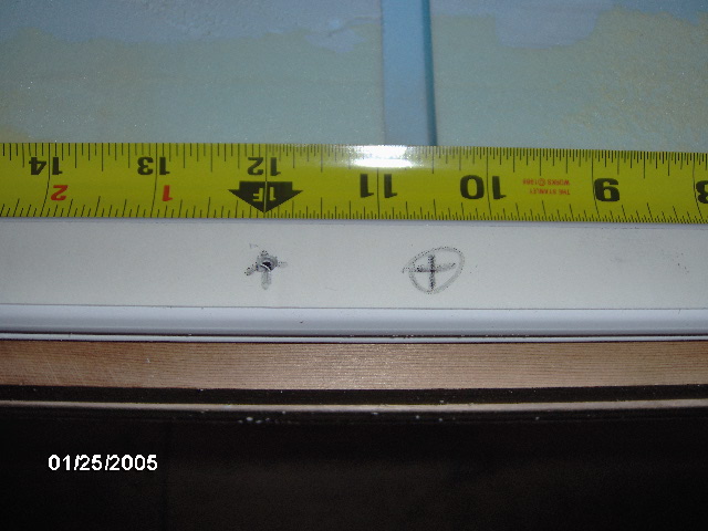
Here I have set up a small block clamped on at 3/4 inch from the front of the wall to help mock up the Wiremold in the correct position for a smooth transition at the corner trim piece, shown. Also note that I have oriented the mold with the open edge up, then flipped it over on its face to lay out the holes on the back/tape side. I will use truss head screws (similar to pan head, but shorter and wider) from the inside of the track to “compliment” the factory installed adhesive tape.
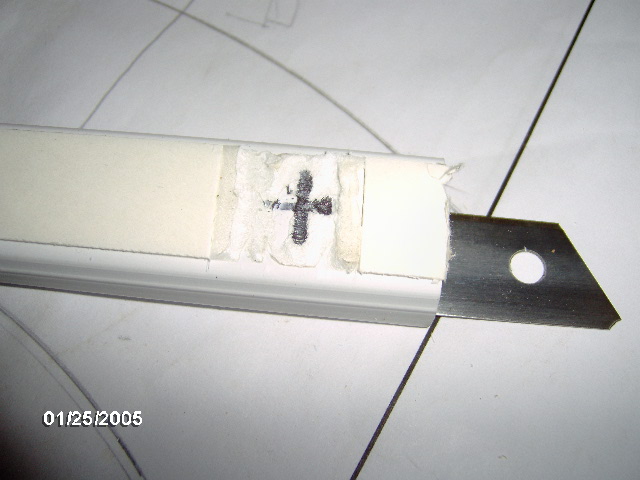
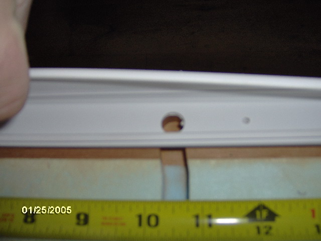
I settled on mounting screws located 3 inches from either end, and at each 9 inches on center in between. Here I am confirming that the marks for the wire pull holes (circled +) align with the routed channels.
To make sure that I only drilled through the back side of the Wiremold I at first stuck a scrap of fir into the molding to stop the drill. After a couple of holes and poking through the wood with the drill (but thankfully not the molding), I switched to a replacement blade for my razor knife, shown here partially installed for the photo op.
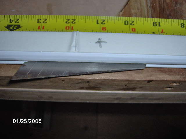
Worked great! Fit the channel perfectly and stopped the drill easily.
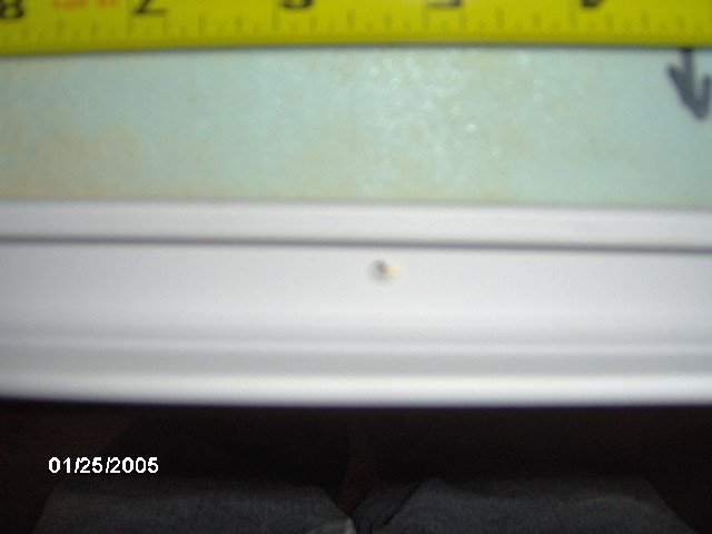
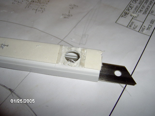
Crappy pic of the resulting screw hole only in one side of the PVC mold.
This is the end of the piece marked for the hole at the street side wall switch wire channel. I decided to cut away the double backed tape before drilling the hole (I needn’t have).
Also note the razor knife blade in true position to prevent drilling through the presentation side.
Karl was visiting, with Simon in tow, and suggested this 7/16 inch slugger bit for cutting a clean hole for the wires to pass through; less chance of biting in and/or shattering the PVC than a double fluted drill bit.
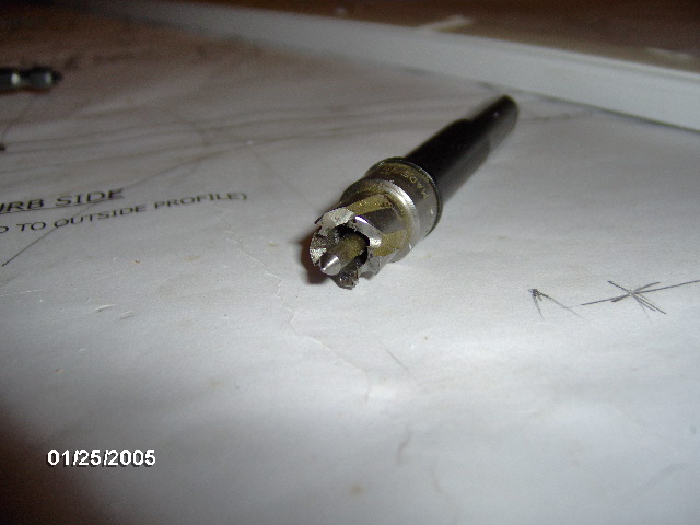
Worked like a charm. Right tool for the job.
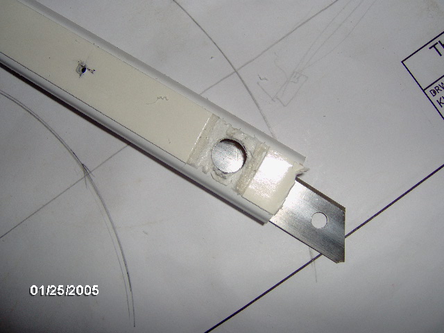
And this shot looking down from the top of the wall showing the dry fit check to make sure that the drill hole aligns to the routed wire channel in the wall.
Haven’t deburred yet.
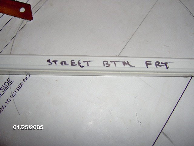
Made sure to label the part in a spot that will not show after installation (along the bottom edge).
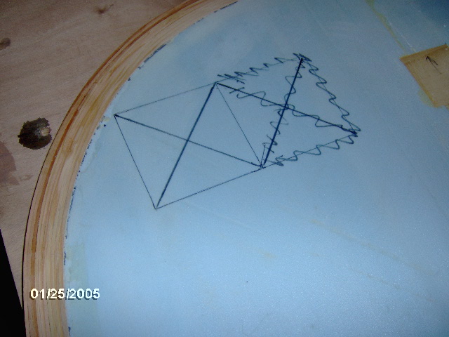
Then I laid out the recess for the “Plan B” hatch strut blocking. The scribbled out lines are where I put the layout ahead of the reference dimension instead of behind, like on the plan.
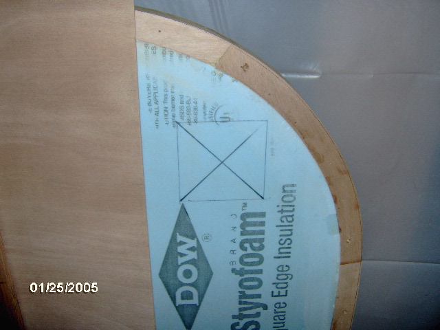
But a quick “dumb idiot check” of the curb side wall revealed the error and I was able to fix it before any harm was done. This is the curb side wall in the pile leaning against the wall.
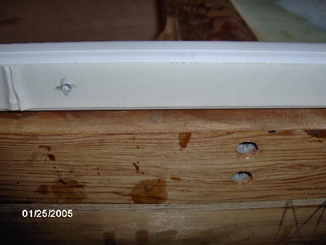
While wrapping up for the night I noticed the deck screws that I had used up through the bottom of the wall sill where I had missed the biscuit slots while gluing up the door jambs. Oops, better double check and make sure that none of the Wiremold mounting screws will interfere with these screws. All clear.

And that’s as far as I got. Progress is progress; many small bites doth eat the elephant.


 the time is drawing nearer.
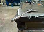


 KC, your wiring is so Well engineered !!!
