This past week has been hot and humid, so while I have been out to Mecca as usual, I haven’t made much progress, nor taken many pic’s until today. With the cold front that drove Arthur out came rain on the 4th, then a gorgeous cool, dry day today. Perfect weather for building!
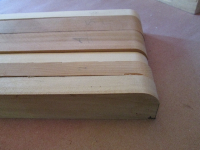
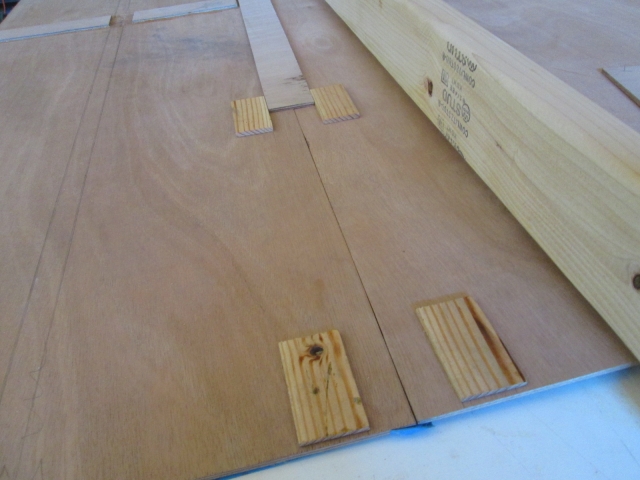
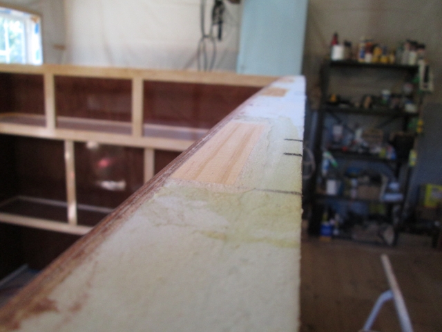
Let’s get caught up. On Monday I futzed around measuring and test fitting ceiling related stuff. The third spar will sit on top of the butt splice backer for the front and middle panels so it needed to be ripped down by 5mm (3/16 inch). Here it is in order with the others after being ripped. You can see that it is no longer as tall.
The 6th spar goes over the rear cabinet, so I had to remove a portion of the butt splice backer on the pieced together rear ceiling section. Here it is dry fit.
On Wednesday I started cutting/chiseling out the pockets for the extra blocking in the tops of the walls where the extra spars will be screwed down into.
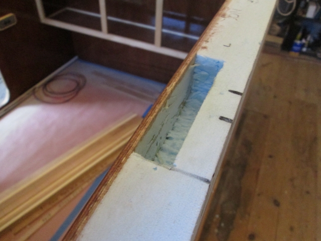
These were purposely fit a tad shallow; I would rather shave the blocks down to the profile after gluing than have them be low.
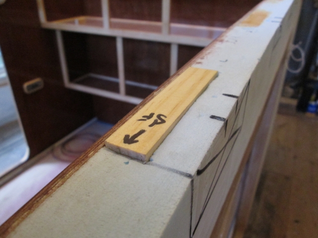
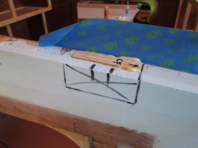
I took the 4th off. Today I finished up fitting the four new blocks and glued them in using the same technique as the others done previously. I masked across the top edge of the inner wall skin to keep GG ooze from dripping down the nice finish, and glued them in. Here the glue is just starting to kick.
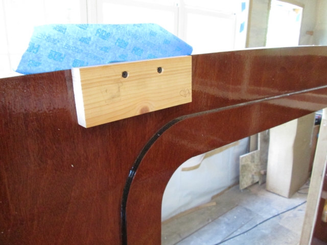
On the inside of each location I screwed a good size temporary block. This pinned the glued blocks into location, helped spread the load so as not to damage the finished wall, and kept the screw heads from digging in. When these are removed there will only be small screw holes that will be filled with the colored putty, and will hopefully virtually disappear.
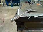
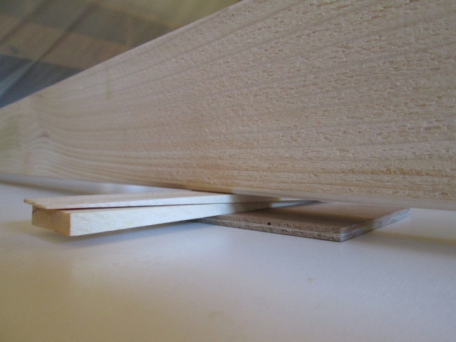
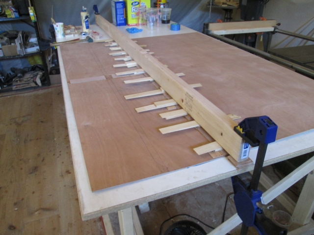
While that was curing I set up this clamp bar bridge. It’s a 2x4 x 8ft clamped to the edges of the work bench on top of 3 scraps of 5mm at each end.
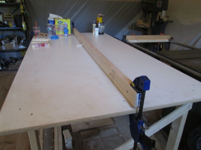
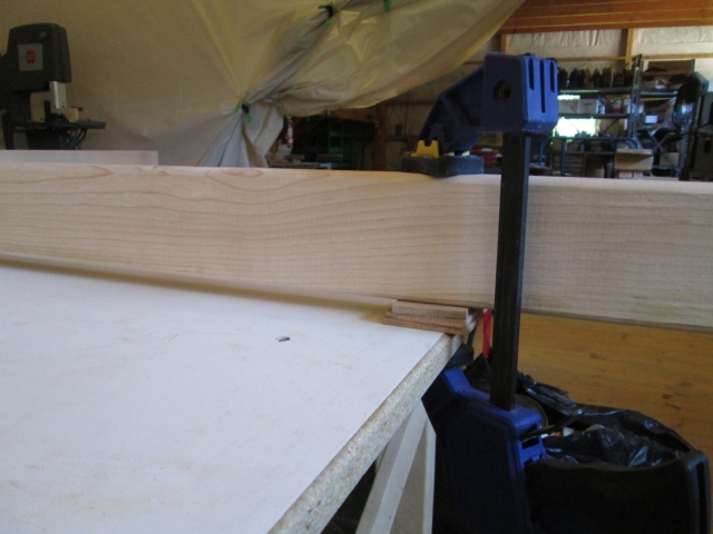
This left a gap between the 2x and table where I could slide the ceiling panel under and use wedge shims to clamp all along the field of the seams.
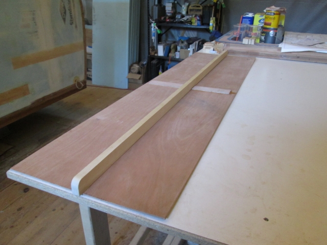
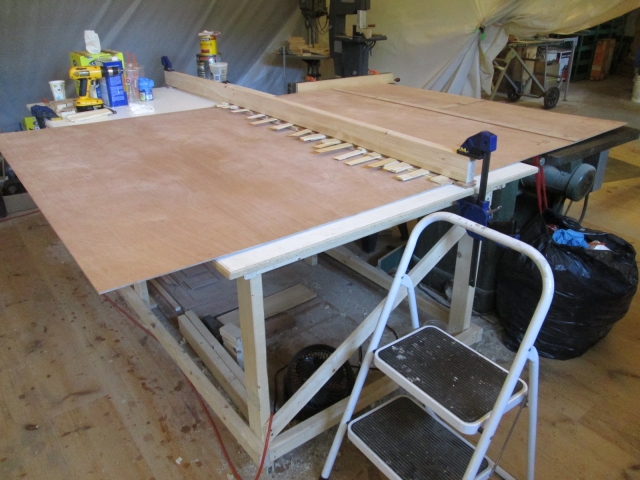
This is the rear ceiling panel on the left, the two piece butt splice backer strip, and the middle ceiling panel under the clamp bar on the right, all ready to be slid under the bar after applying the glue. The small shims of fir on either side of the backer are temporarily double sided taped on to help position the backer and keep it from sliding around in the glue.
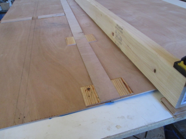
Since this seam will be glued onto the top of the rear cabinet face frame, I hadn’t bothered to make the butt fit perfect, and with the slight gaps here and there it seemed like more glue would ooze thru it than would fasten it, so I let the backer do the work and didn’t bother to try to glue the edges of the panels. Here it is under the “clamp”.
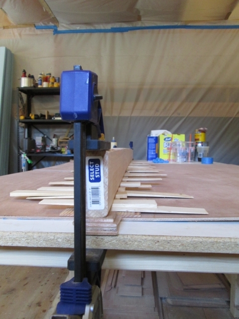
Even with the 2x4 on edge, the wedges are a powerful tool and put a goodly arch in it; and then it would relax and the shims would loosen up. So the process was put the wedges in, go back and re-shim all of the loose wedges until they were all about the same snugness, wait a little bit, then go back and snug all of the wedges back up again.
As the GG was oozing out of the wall blocking, I went around and scooped some of the excess off to keep it from dripping down the outside of the walls. Apparently I had used plenty to make up for the slight roughness of having gouged out the pockets.
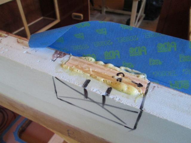
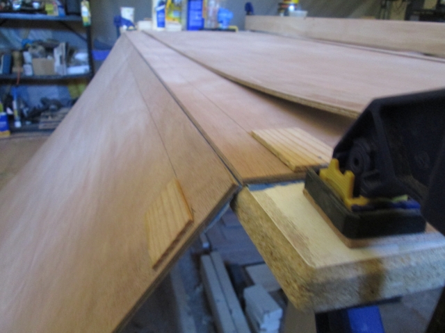
Here is an example after removing the masking, cutting the excess glue, shaving the blocks down close with the block plane, and finally sanding flush with the little hard block.
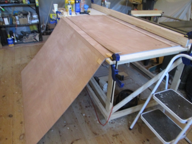
Next, I took care to match the two edges of the rear ceiling panel assembly and the front panel. For this seam, the main ceiling seam in the cabin that will be visible, I improved on the technique that I used to join the two halves of the rear ceiling panel together. Before taping along the seam on the good/bottom side, I taped along both sides of the seam first. That way if the tape holding the seam together should happen to separate when I folded the joint open to apply the glue, at least the wood would still be protected and hopefully not get glue on the face. It actually worked out better with the longer sheet because when I dragged it off the front of the bench it touched the floor without opening fully to 90 deg’s. The angle tended to match the chamfer on the edge of the bench, backing up the tape and keeping it from pealing open further than intended.
So with it in this position, with the backer piece traced out and near at hand (the curled up piece), I applied glue to all surfaces; inside the butt joint, adjacent to the seam, and on the underside of the backer.
Then I slid it back up on the table, flipped the backer into position, slid it under the 2x4 bar, and wedged it up.
Since I couldn’t really reach the middle of the table, the step stool was handy by so I could climb up and sit or kneel on top to work.
I still haven’t decided if I will attach the spars, using the same clamp and glue technique, before or after applying the finish to the underside of the panel. As it is now the panel is mostly flat and I can work the finish fairly easily, but the finish could be marred when I add the spars. If I add the spars now I might have a harder time sanding with the panel only partially supported, but I suppose I can use temporary blocking to prop it up securely (the way I am leaning at the moment). I’ll also have to factor in the roof vent riblets, as well.
All for now.


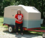
 Getting excited! All the planning is coming together.