Grounding improvements are in two separate sections; lightning rods or air terminals and grounding (earthing) the electrical system.
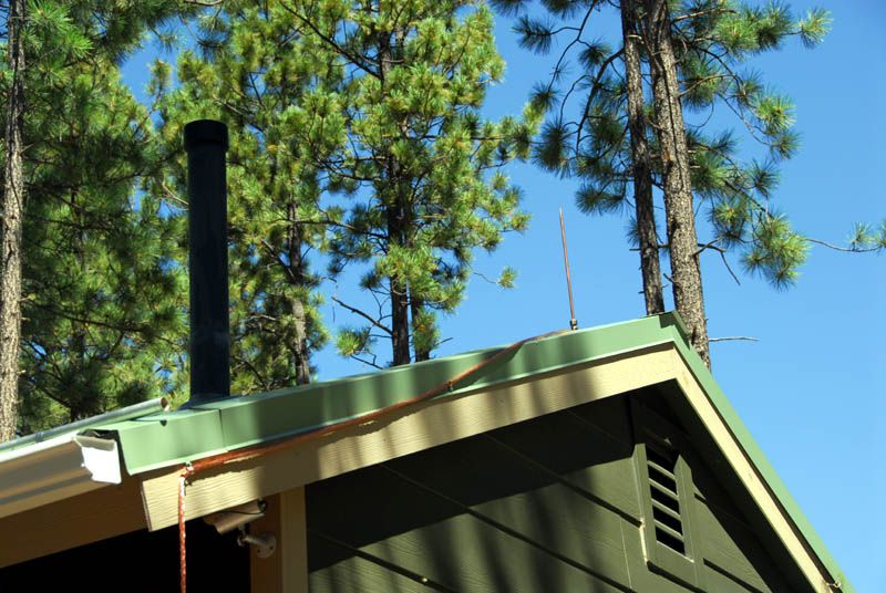
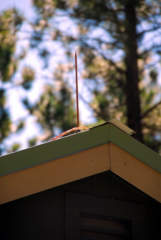
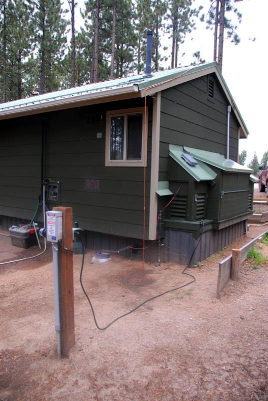
Air terminals. Four on the 16 x 30 cabin, 3 on the ridge and 1 on the S/S wood stove chimney. 26 strand 7/16" dia. wire used to connect all the air terminals. These extend down to the ground at diagonally opposite corners. Each wire first connects to an 8 ft. copper clad 5/8" dia. steel rod that is driven into a hole dug to make the bottom end of the 8 ft. rod 9 ft. below grade and set out from the cabin wall about 2 feet. The same wire is buried in a trench to run to a second rod about 10 feet distant on each side of the cabin. From that rod the wire extends another 10 feet or so to a 2 sq. ft. copper sheet buried about 2 - 2 1/2 feet down. All wires are covered with earth. The terrain was reshaped slightly in places to permit the collection of rain water and snow melt to soak into the soil and make a better ground electrical connection.
The shed (8 x
 has a TV antenna mast that reaches a height of 24 feet above roof level. This mast is down wire connected to a ground rod. A wire connects this ground rod to one of the ground rods at the cabin, a distance of something like 15 - 16 feet.
 The barn (larger shed, 9 x 16) has two air terminal on the high side of the shed style roof. These are connected with the same 7/16" wire as used on the cabin. Here too the down wires drop at diagonally opposite corners. There are 2 ground rods at each corner, placed about 10 feet apart. One of these ground rods is connected to the ground rod at the TV mast. So all ground rods are inter-connected for best performance. Resistance between 1st and 3rd adjacent ground rods ranges from 2 to 6 ohms. That may change over the span of the seasons. The ground is mosit right now. We'll have to resample later in the year and next spring and early summer. Several access points have been made to facilitate the re-measuring.
Electrical system grounding. This includes the ground rod system and the new surge suppressors or lightning arrestors.
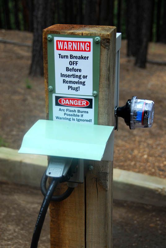
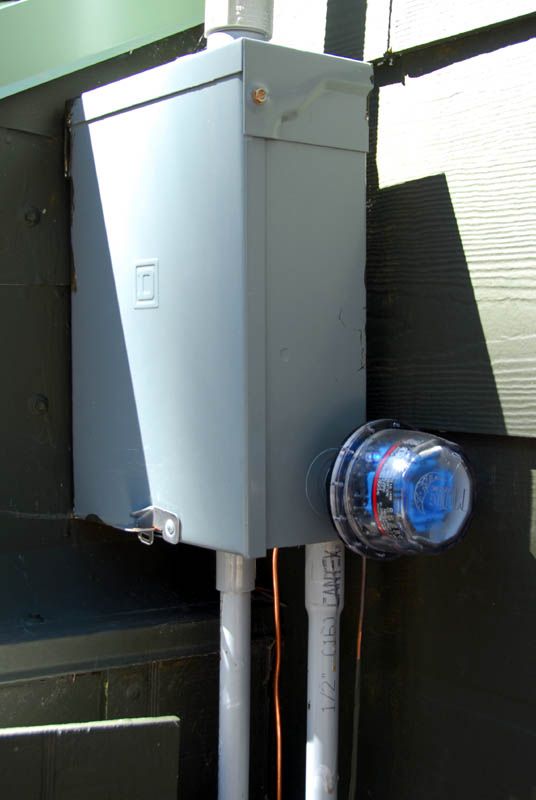
I have Midnite Solar SPD's. One at the PV array combiner box. Another is 310 feet up the hill at a newly installed "power post" that is 10 feet from the cabin corner where the new Midnite Solar "The Kid" charge controller is located. A third MN SPD is located right at the CC input . A fourth is located at the DC wires that feed the inverter; this is a low voltage version as it is connected to the 24 VDC battery bank. Finally a fifth MN SPD is mounted at the AC service panel. At the PV array is also a Delta DC suppressor as well as a Delta AC version suppressor at the service panel. Nothing like redundancy.
 And expense.
  A cool thing about the MN SPD is they have an LED that indicates that it is operational.
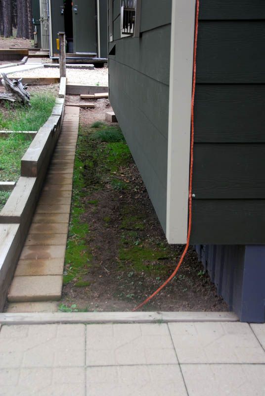
Grounding. At the PV array I added four rods in a manner similar to the lightning air terminal system. That is rods connected to one another in a string with about 10 feet between rods. They extend to the pond area with the last rods directly parallel to the bermed low side of the pond. Probably the most moist area we have. At the cabin all the hardware from CC to inverter, battery charger and service panel are individually connected to a ground buss. One end of the ground buss is connected by #2 copper wire to a ground rod at the new power post. From there a series of 5 ground rods extend into the grey waste water dispersal field. On the surface a series of bowls, centered around the rod positions, serve to catch, retain and permit soaking in of any precipiation.
Presently we are using a backup Samlex 1500 watt pure sine wave inverter for the cabin AC power needs. It does mean having to think when using the microwave or electric kettle. It will do until we decide if we really need the power capacity and convenience of something like the 3500 watt Outback that was toasted.
Lastly there does appear to be some hidden wiring damage in one of the lines to or between the gazebo, shed and/or barn. On occasion the GFCI that feeds that low use line trips. Sometimes it will not reset, sometimes it will reset several days later. The GFCI itself is good. It will be a tedious task to track down. Hopefully I'll track down the fault earlier rather than later. That's the Labor Day weekend project.


