I decided to work on something less physical this afternoon after having to work at my day job until about 1pm. So starting to rough in the wiring for the side clearance lights seemed like a good idea.
The recessed pockets that I cut behind the lower marker lights are kind of small without much room for extra wire or splices, so I decided that I needed to take a closer look at how those would go before deciding how to tie the wires for the upper clearance lights in.
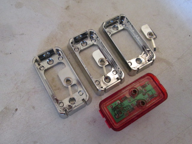
When I picked the marker lights I based the decision on the following in order of precedence: 12v LED; surface mount; their basic somewhat retro/generic appearance (simple but not too flashy); and inexpensive price. I also liked the fact that the bezels screwed down first and the light assembles snap into place so that the screws will be hidden. What I didn’t do was pay too much attention to how they would be wired. I think superbrightleds.com has updated their website with lots more pictures and info than when I bought these, but to be honest I probably didn’t consider it much at the time. The specs said they had a hot lead attached, but in fact they have a pair of female bullet terminals imbedded in the back (see pic below) and a pigtail with a male bullet included for the hot lead. The ground terminal nests into a rivet ring with tab in the mounting base and the tab gets pinched under one of the mounting screws to complete the circuit back to a grounded chassis. Since I will be screwing this thru the painted canvas into the wood sill of my walls, I knew I would have to hard wire the grounds, figured out what size and type of bullet connector to buy, and got those sometime back.
Well, it turns out that the bullet connectors I bought, although straight like the one provided, are of much better quality, thicker material, with a longer shank and insulator, so they would stick out further behind the fixture. Also, when fitting the light into the bezel the extended part of the female terminal that sticks into the rivet ring didn’t seem to fit with the bullet installed. If I snapped the light into the bezel first, the bullet couldn’t be pushed thru the ring into the terminal because the terminal was pinched closed slightly by the forcing cone action of the ring. So, since the problem was the OEM grounding feature that I couldn’t use, didn’t need and was causing me problems, the solution was to cut them out. Here you can see the as built bezel on the left; the bezel in the middle marked for cutting; the bezel on the right after cutting the ground feature out; and the back side of the lamp with the female terminals.
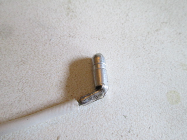
Still, the good bullet terminals I bought would stick too far out the back, and I didn’t feel like having to order the 90 deg type. So I looked at them a little closer. I frequently strip off the factory insulation on this sort of thing so that I can make solder connections. From there it looked like I could bend the crimp portion over almost 90 deg; except that in bending it the crimp area got crushed so I would have to solder the wires in before bending.
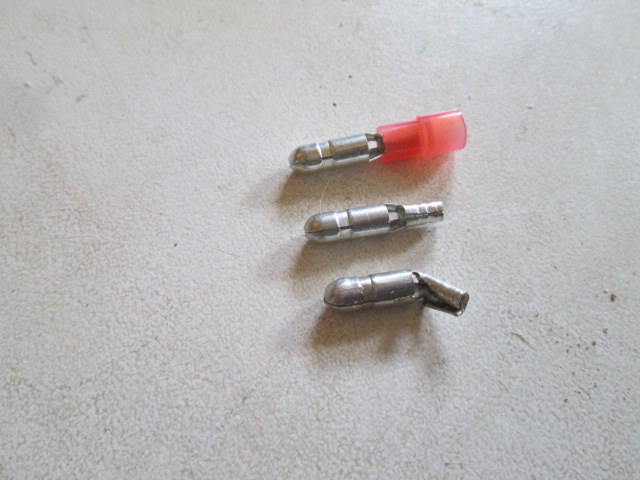
Here’s one soldered first then bent, followed by the shrink tubing.
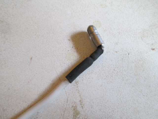
I did find that if I didn’t bend them straight over that the shell could tear or crack open a little, so careful inspection, a little solder, or just try again; I have 50 in the pack and only need 8 good ones.
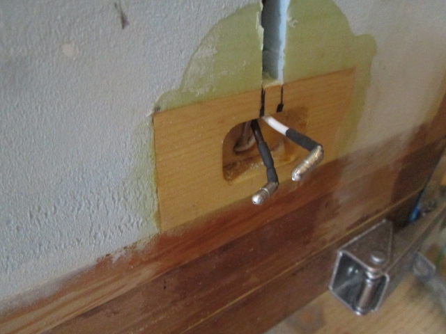
To solve the problem of having extra wire to deal with, I decided to use the extra wire I had left at the marker light rough in to move the splice up into the clearance light wire way. By doing this I can set the third leg length from the tee splice so that the bullet just sticks out a little bit, but there is still enough wire to work with, and if I had to I could pull the upper clearance light out from the end of the line and retrieve the extra wire or rebuild the end of the harness as needed. So here are the two bullets at the marker light…
… the splices staggered a little higher up…
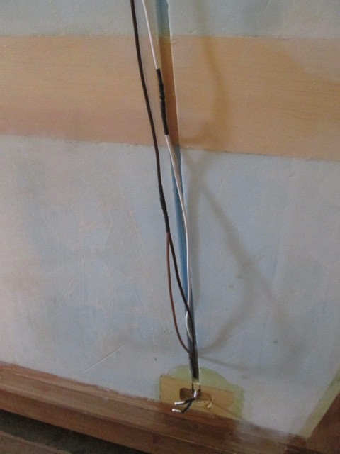
… and an overview.
Just need to do that 3 more times.


 Best find help to make it easy on yourself...