I spent most of the weekend wiring the teardrop and made good progress. All that remains is to run the 8 gauge wire to the car, wire the hatch after I build it, and wire the running lights under the trailer.
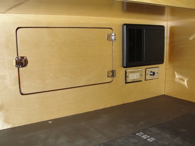
PD 4045, a 12-volt outlet, and a 110-volt GFCI outlet are located under the dog kennel. I ran an extension of this 110 circuit to the storage area under the air conditioner. This is where I'll plug in the A/C.
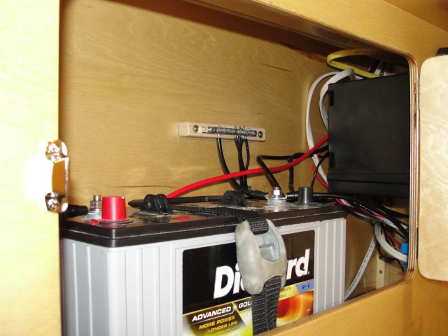
The battery is stored behind the door. I'll tidy this up when I remove shore power and the PD 4045 to install the aluminum skin. The grounding bus is in view. I also wired in a 30-amp fuse between the PD 4045 and the battery.
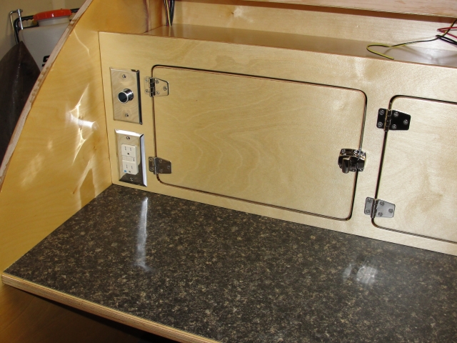
A 110-volt GFCI outlet and a 12-volt outlet service the galley. The wires run up the left side wall into the ceiling.
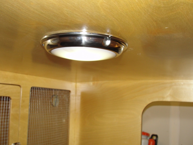
We're quite pleased with this marine LED dome light with touch control.
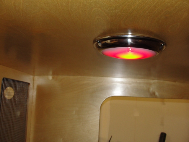
The dome light also switches between white and red. We're installing one of these in the galley lid. Supposedly bugs are less attracted to red light.
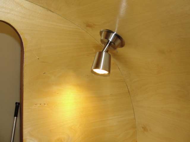
The LED reading lights cast just the right amount of light and are cool to the touch. This picture also shows my mistake on the walls. I didn't smooth the curve prior to routing the ledge. This created small gaps where the ceiling meets the wall. I'm going to experiment with a narrow, colored caulk bead throughout the camper to mask imperfections and seal things up better.
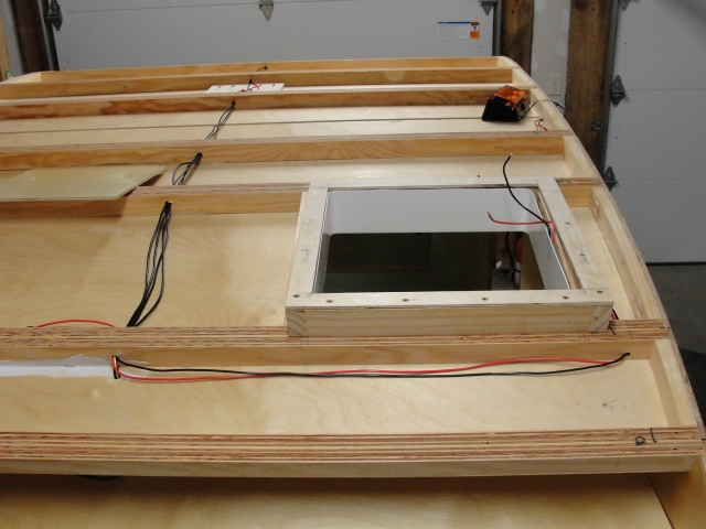
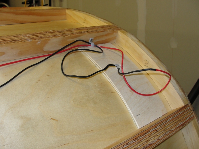
View from galley. I ran a ground line to each circuit. The two porch lamps share a circuit and the reading lamps/cabin dome light also share a circuit. Junctions are soldered, secured with a wire nut, and taped. Splices are soldered, heat shrinked, and taped.
I ops checked the exhaust fan and discovered the remote doesn't work to increase the fan speed. That' a non-starter since the manual controls are located above and behind the air conditioner and almost impossible to reach. We'll see how timely warranty support is with these Max Fans...
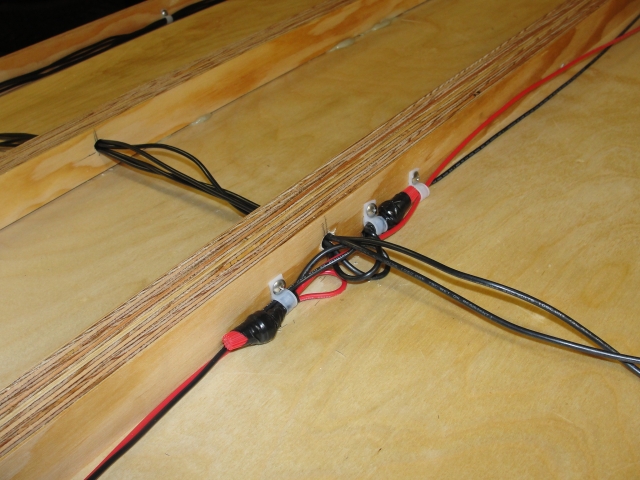
Porch light junction.
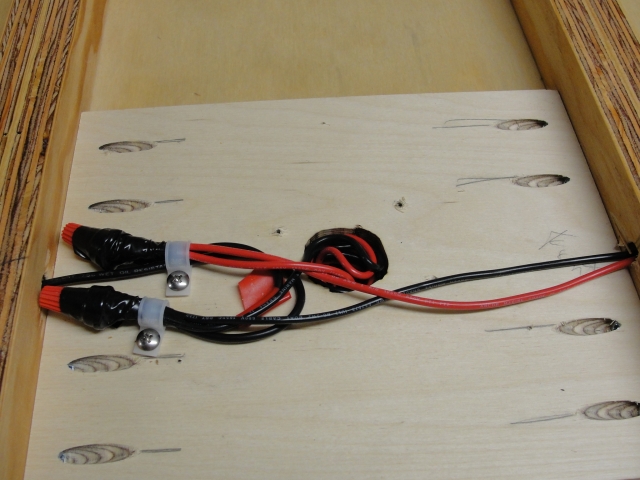
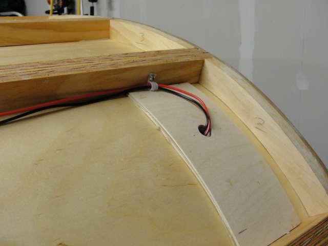
Cabin dome light junction. I pocket screwed a piece of 1/2" plywood to support the light on this flat span.
I had this wired last night and realized that I had no slack for future light repair/replacement. I removed the wiring and fixture, cut a bigger access hole, rewired, and coiled the extra slack in the larger hole. Now I can make any future repairs without having to remove the roof!
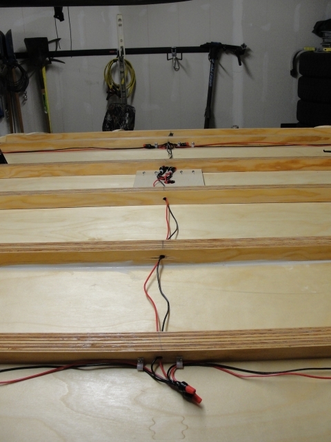
View of reading light junction.
Wired with repair slack.
Slack tucked into fixture. Notice how I reinforced the area for mounting the light. I cut two layers of 1/8" plywood, applied polyurethane glue from a caulk tube, and held things in place over night with clamps set on the edge of the roof spar. It worked well.