PD4045 Step by Step
Disclaimer: I am not an electrician, and the sources of this information may not be electricians either. Use at your own risk - I’m using at my own risk.
Why this guide: The installation manual provided by Progressive Dynamics may not have been intended for layperson use. Regular people have not found it particularly enlightening, and thus forums and blogs are full of Q-and-A style advice on this topic. I need something a bit more systematic and orderly than Q-and-A, so I’m compiling this guide for myself.
This guide does not include:
- Solar power generation
- Inversion from DC to AC
- Charging a battery from a tow vehicle
- Integrating a generator
This guide does include:
- 120v AC circuits
- 12v DC circuits
- Charging a battery from AC
Supplies:
- PD4045
- Shore power inlet
- Circuit breakers - single or tandem
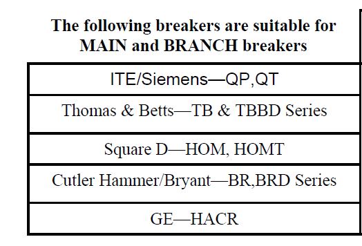
Fig. 1 - Compatible types of breakers.
- Fuses
- Devices, appliances, fixtures, etc.
- Wires
- Larger (lower gauge) wires to battery and shore power, typically 8 or 10 AWG
- Smaller (higher gauge) wires to fixtures, typically 12 or 14 gauge for AC, smaller for DC
- Battery (optional)
About the Word “Ground”
There is a great danger involved in describing AC and DC current in the same document, and that danger is the word “ground”. This one word has two very different meanings, thanks to the automotive industry, and getting the two meanings confused can result in electrocution.
In AC electrical systems, ground and negative are not the same. Negative returns current back to the electrical mains. Ground takes any stray current and directs it to Planet Earth. For that reason, in the UK they use the word “earth” to mean “ground”.
In non-automotive DC applications, the wiring is positive and negative only. Each fixture has two wires, one of which routes to the positive battery terminal and one to the negative terminal.
But in automotive applications, negative wiring is not accomplished with actual wires. Fixtures have but one wire to the positive battery terminal. Instead of using a negative wire, fixtures send current into the metal frame of the vehicle, using it as a route back to the battery. This is casually referred to as “ground”. Thus, in this context, ground and negative are the same.
For that reason, in this document, the word “ground” is not used at all for the DC portion of the wiring. If your trailer, tiny house, or other structure uses a metal frame that is accessible for routing electricity, you are free to do that. But this document will instead refer to negative wiring, which someone with a wood or fiberglass structure without easy access to the frame is likely to use.
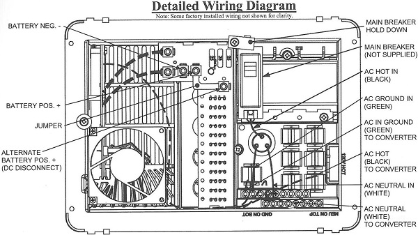
Fig. 2 - The wiring diagram provided with the installation guide.
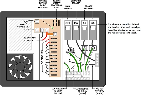
Fig. 3 - Zac’s much clearer diagram with an addendum.
Steps
- Hopefully you planned the AC and DC circuits before this point, evaluating the load needs and power sources. This would have been how you decided on the PD4045 in the first place.
- Obtain a PD4045 distribution panel. Be careful, there are dangerous counterfeits on the market. Ask around for a reputable source. I got mine from Vintage Trailer Supply.
- Connect the shore power inlet to the PD4045.
- The shore power inlet is a topic for another guide. You’ll be running appropriately gauged hot, neutral, and ground wires from it to the PD4045.
- Shore power hot (black) goes into the bottom of the main breaker. When this breaker is clipped in, the clip in the back of the breaker makes contact with a metal bar; it’s a different sort of buss bar than the ones for neutral and ground. This is how power is distributed to the other breakers.
- Connect the white and green wires to their appropriate buses as shown in the illustration.
- Connect the wires from the breakers to the fixtures.
- Single breakers serve one circuit per gang (breaker location). Tandem breakers serve two - and each breaker in a two-breaker tandem unit can have same or different amp ratings.
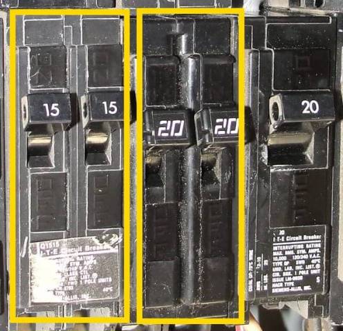
Fig. 4 - Two tandem breakers vs. a single. - One of the breakers needs to send current to the converter. You can also run fixtures and such off this same breaker, if you like. This is what’s going on in the Fig. 3 above, where hot from the 15 amp breaker goes to a buss bar before going to the converter. Other fixtures can then be attached to that buss bar. The black (hot) wire that goes to the converter is already installed by default, along with the white (neutral) and green (ground) wires. White and green are already attached to their respective buses, while the black is loose due to waiting for me to install the breaker for it. Note: Units produced since January 1, 2016 don’t have the hot buss to converter, as it’s not really needed. See the announcement on their product page for more information.
- Connect the other breakers in the same way. Run hot wires from the bottoms of these breakers to their various circuits. Run neutral and ground wires from the fixtures to the appropriate buses.
- Single breakers serve one circuit per gang (breaker location). Tandem breakers serve two - and each breaker in a two-breaker tandem unit can have same or different amp ratings.
- Connect the breakers. Clip them into that aforementioned buss bar in the back.
- Connect the wires from the fuse panel to the fixtures. One wire is already provided for each fuse to make its corresponding circuit. (Some people use a buss bar to combine fixtures into the same circuit. It is important to consider the draw of all of these together, along with the capacity of the wire and the fuse.) The other wire from each fixture should come back to a buss bar. This is your DC negative buss bar. More on that in steps 8 and 9.
- Connect the fuses to the fuse panel. Hold onto the edge of the board while pushing each fuse in. These clips are pretty tight. As you plug in each one, test the circuit to make sure it’s good. User noseoil suggests using a a small 12 volt AGM battery (alarm panel battery from a house or business, 1.5 amp hour) with alligator clips attached for this purpose.
- If no battery, run a wire from the DC negative buss bar you set up in Step 6 to the lug marked in Fig. 2 as BATTERY NEG. -.
- Connect the battery, if any.
- Connect the black battery wire from the negative pole of the battery to the negative buss bar you set up in Step 6. Connect another wire from the negative buss bar to the lug marked in Fig. 2 as BATTERY NEG. -.
- Connect the red battery wire from the positive pole of the battery to the positive lug marked in Fig. 2 as BATTERY POS. +.
- Test with multimeter.
- Test with live power. Plug in shore power and test all fixtures. Look for smoke and/or funny smells.
Cutoff Switch / Breaker / Fuse to Battery
If you are connecting a battery to the converter side to charge it, then you need at the very least a fuse close to the battery, between the battery and converter. Some people (8ball_99) use an external breaker, so that the breaker can be reset, and also because a breaker can be used as a cutoff switch. Some (MtnDon) use a type T fuse that blows quickly in case of overload, for greater safety.
It is important to be able to cut power to the battery when not in use, in case of a short. Whether to do this with with a fuse or a breaker or a switch is a matter of convenience and personal preference.
The PD4045 provides a way to wire the battery cutoff into the unit. There’s an L-shaped jumper that connects the positive lug to an additional lug. If you are using a cutoff switch, you remove that jumper and put the switch in place of the jumper to connect those lugs together. You’ve just added a way to shut off the connection between the lugs.
I don’t see the benefit of putting the switch in this way, though, as opposed to putting it in the line coming off the battery, which should work just as well and which some people prefer.
Grounding the Frame:
There needs to be a path from the frame to AC ground, in case a hot wire contacts the frame. Without such a path, a person entering or leaving the trailer could become the path to ground and be electrocuted. Run a green wire from the ground buss to the frame.
Warnings:
- Make sure the unit has adequate ventilation.
- There is a right side up. Don’t mount the unit sideways or upside down.
- Don’t mount the unit in the same compartment as gas or a battery.
- Mount the unit in an interior and dry location, not in a wet or damp location.
- When connecting to shore power, first test the pedestal or outlet you are connecting to. It’s important that the outlet be wired properly, and sometimes they’re not.
- Common faults are reversed polarity and open neutral. There are testers for this purpose.
- When connecting to shore power, it’s also good to use a voltage regulator and surge protector. AC power supply can be dangerously unstable, so it helps to have a buffer.
- If you want to be cool like me, you can get one unit that does all that testing and protection in one go. I chose this one.