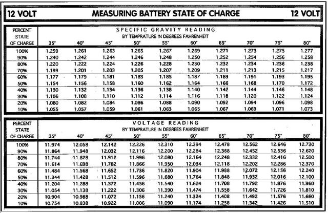
Battery management systems are simple in theory. Using a current monitor, only put as much current back into the battery as you take out. Instead of maintaining a constant 13.8 volts (V) or thereabouts, a battery management system checks the battery's state-of-charge (SOC) when the engine is off and when current flow is essentially zero. From then on it will target a SOC of 100 percent or less in order to save fuel, avoid overcharging and extend the life of the battery.
The ECM and/or BCM remain the brains of most charging systems, but there are standalone systems as well, notably GM's Stand Alone Regulated Voltage Control (SARVC). In either case, a small current monitor built into the battery terminal or placed around the cable provides information regarding current flow in or out of the battery. By adding up all the current flowing in and out of the battery, the ECM or a standalone module can determine any net gain or loss to SOC.
Sensing Current, Voltage and Temperature
Bosch battery current sensor monitors current, voltage and temperature.
Current sensors built directly into the battery terminal from Bosch, Hella, Delphi, and others provide current, voltage, and temperature sensing. GM uses a Hall effect sensor placed around the battery cable for current monitoring and monitors temperature and voltage elsewhere in the system. Non-Hall effect designs typically utilize micro-ohm shunts capable of measuring large amperage flows during cranking all the way down to parasitic draws of 30mA (milliamps) or less. Hybrids such as the Prius extensively use current monitoring for both main battery and motor monitoring functions. Because of their widespread adoption, techs will need to become familiar with current sensors. Most will display amperage data as a Parameter Identifier (PID) on a scan tool providing a value which can be compared to a reading taken from a clamp-on ammeter.
A shunt-style current sensor is merely a very low value resistor, in the range of 50 to 100 micro-ohms (millionths of an ohm). This provides enough resistance to create a measurable voltage drop but not enough to interfere with cranking. A 200 amp starting current passing through a 50 micro-ohm resistance will only produce a voltage drop of 0.01volt.
GM Stand Alone Regulated Voltage Control has six different modes listed on an attached chart.
Current sensing is only one piece of battery management. Battery temperature sensing is already in widespread use to vary the charging rate on vehicles. Traditional charging systems adjust the alternator setpoint (12.8-14.5V) depending on the temperature of the regulator. Certain Chrysler vehicles use temperature sensors plugged into the battery tray. When a battery is cold, it can be charged harder and faster than when it's hot. Thermistors incorporated onto certain older GM vehicles' battery cables perform a similar function.
When temperature sensors fail, get damaged or unplugged, "strange" charging behaviors can result. For example, a "failed high" sensor on a Chrysler can cause the alternator to refuse to put out sufficient charging voltage. It can also prevent certain emissions monitors from running, an interesting "gotcha!" A Battery Volts Out of Range DTC P1630 may accompany a failed GM thermistor. Typically a battery temperature sensor is a simple thermistor and can be checked against specs with a Digital Multimeter (DMM). Normally DTCs will set for a shorted or an unplugged connector — but not always, as was recently reported on iATN (
http://www.iatn.net) in a techhelp posting on a 2007 Caddy with an underseat battery.
Sending Sensing Information
A current sensor may transmit information to the ECM directly or via a low-cost LIN bus, Flexray or CAN bus connection. A databus-attached sensor that fails to respond to a query may set a DTC. In the case of GM, the Hall effect sensor utilizes a direct connection to the ECM or battery control module. Generator performance is monitored through the generator field duty cycle signal circuit. This signal is a 5 volt PWM (pulse width modulated) signal of 128 Hz. PWM ranges between 0 and 5 percent and 95 and 100 percent are used for diagnostic purposes.
Sensors built directly into the battery terminal or tray are located in the worst possible place for corrosion and damage from battery acid and fumes. When a sensor fails to provide correct current flow information or loses its connection with the ECM, erratic charging behavior is often the symptom. But be sure you actually have a problem.
Seemingly "unusual" charging behavior such as no alternator output at idle can trip up techs. It may actually be the work of a system working as intended. Take for instance GM Regulated Voltage Control, whether in its regular or "standalone" version. This charging system has six different modes listed in the attached chart. One even attempts to reduce sulfation of the battery. Someone accustomed to seeing the voltage gauge on the instrument cluster pegged at 13.8V is likely to wonder when he or she first encounters a GM vehicle where the voltage varies anywhere from 12.4 to 14.8 during normal operation. Hundreds of Internet postings attest to owners bewildered by this phenomena. A GM TSB attempts to alleviate customer concerns.