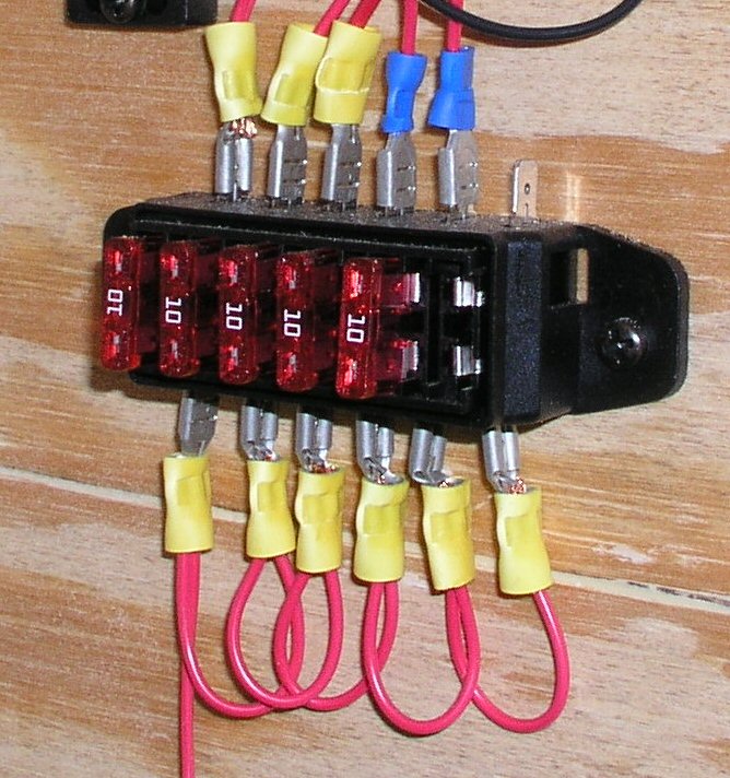
benzu wrote:As you can see in these pictures these wires are not 12 ga or 10 ga they look more like 14 or 16ga
Looks like 18 ga to me.
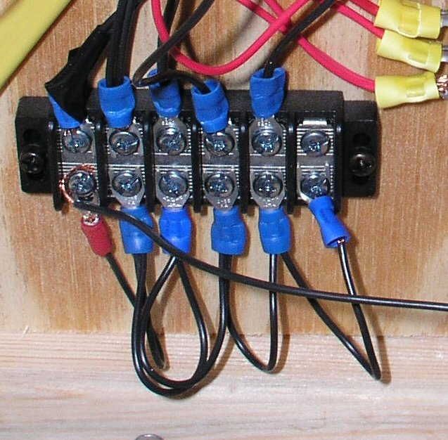
benzu wrote:I still have the problem of the terminal strip. In this picture the negative looks like 16ga or smaller. Don't I have to use the same gauge of wire for the negative as I do for the positive?
Ideally, yes.
benzu wrote:...I have the same terminal strip as shown in this picture and it only allows for smaller then 14ga wire to fit.
In terminal strips like these, the limiting factor for wire size is the spade terminal, not the terminal strip. The picture shows blue connectors which are designed for 14-16 ga wire. If you can fit blue connectors into your terminal strip, you should be fine, but you will not be able to daisy chain or loop the wires from one terminal to another as shown in the pic. To solve this, they make terminal jumpers or buss bars to connect two or more terminals on the strip. There are several sizes available depending on screw size and spacing. (They are about $ .05-.11 each from
waytekwire.com and there is a $5 minimum per line item, so you may have to buy nearly 100 of them. Waytek part #'s 37211, 37212, or 37214)
For the main 10 ga negative wire you will need to find
"narrow block" spade terminals, Where I get them, they have to be purchased in packs of 100 ($15.72 from
delcity.net Part #660365 for #6 screw, part #660385 for #8 screw, or part #660305 for #10 screw).
With a little searching, you may be able to find similar products available in smaller quantities. The examples I have given are only from the suppliers I deal with regularly.
delcity.net and
waytekwire.comAll that being said, I would like to suggest something completely different. In a situation like this, rather than using a terminal strip, you could use one of these:
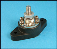
It has a 3/8" stud in the center that is connected to 8 #8 screw terminals. I would also consider using one of these for the positive side, rather than trying to solder all the push terminals on the supply side of the fuse block together. They're about $12 ea, and would save you a lot of hassle and allow for easy future expansion of your electrical system.
benzu wrote:I'm really confused everyone is saying one thing then showing another. How do I do this?
Hope this info helps you. Good Luck!

Joe G


 . Keep in mind when designing a circut that the fewer and cleaner, i.e. soldered connections you use the safer and more enduring your finished product will be . KEEP IT SIMPLE AND SAFE. Just my two cents worth. Have fun!!