Wiring for lights

Anything electric, AC or DC

Wiring for lights

Postby rhltechie » Mon Aug 18, 2008 3:19 pm

Hi all,

I was doing some sketches last night and had a question about the wiring of the TD. I will be having a few lights spread out throughout the cabin and then some porch lights. My question is this, I have never daisy chained anything when doing wiring for speakers or data networks, its always been a no no for me. I could have sworn I saw somewhere on the site where people are daisy chaining their lights and not doing what I call “home runs” for every light. Is there some good reason to daisy chain other than your TD lights going out not being the end of the world?

TIA,

R
User avatar
rhltechie
The 300 Club
 
Posts: 378
Images: 49
Joined: Sat Aug 16, 2008 9:11 am
Location: South Carolina

Postby mechmagcn » Mon Aug 18, 2008 4:17 pm

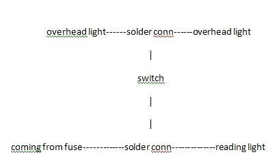
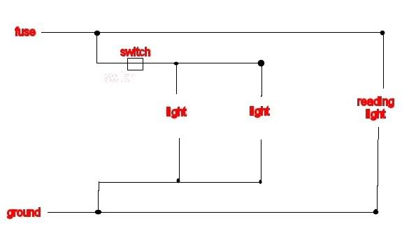
As long as the total amp draw of all of your lights doesn't exceed the rating for the choice of wire, there is no reason to not run multiple lights from one run of wire. In wiring my TD, where I have made connections to the main wire, I have soldered the connections and then covered that with liquid electrical tape.
Jeff & Micki
53 F100
Mercedes turbo diesel
Teardrop "finished" as if they ever are
You can never be lost if you don't care where you are going!
User avatar
mechmagcn
Donating Member
 
Posts: 813
Images: 56
Joined: Mon May 05, 2008 9:47 pm
Location: Moro Bay, AR

Postby rhltechie » Mon Aug 18, 2008 4:19 pm

Thanks for your reply. Do you use some sort of splitter at the point you are to go to the next light? do you do this for the "hot" wire as well as for the neautral wire?
User avatar
rhltechie
The 300 Club
 
Posts: 378
Images: 49
Joined: Sat Aug 16, 2008 9:11 am
Location: South Carolina
Top

Postby tinksdad » Mon Aug 18, 2008 5:01 pm

Have you checked the cost of copper wire lately? DUH!!! Of course you have. A tear drop may be small: but all those individual home runs would add up to some serious length rather quickly. And then add a fuse for each run and your fuse block is going to get rather large as well. Putting multiple lights on one run makes economical sense. I think it was high school physics, but wiring multiple devices in parallel (being mindful of amperage draw of the total number of devices on the run) and you don't get the cheap Christmas tree light effect. If one goes out, they don't all go out unless the fuse blows.

As far as the connections. on all but the last in the run, you would have a hot wire coming in, a hot wire going out, and the device hot wire as well. The same for the ground side. Connect the sets of three with a small wire nut or solder them together and insulate with some electrical tape, liquid rubber, or heat shrink tubing.

It was a personal choice; but I put my exterior lights on separate circuits from my interior lights. The twelve volt power plugs are separate circuits, as well as the stereo system and the roof vent fan. I'm using 5 fuses on a 6 fuse block panel (available at Auto Zone for around $5).
User avatar
tinksdad
500 Club
 
Posts: 966
Images: 155
Joined: Mon May 05, 2008 9:20 pm
Location: Olive Branch, MS
Top

Postby mikeschn » Mon Aug 18, 2008 5:04 pm

I think the key here is NOT to do any splicing under skin where you will never have access to it again.

If you are going to daisy chain lights for example, make sure all your runs end in a cavity where your lights are, so you can fix, repair, replace etc...

Mike...
The quality is remembered long after the price is forgotten, so build your teardrop with the best materials...
User avatar
mikeschn
Site Admin
 
Posts: 19202
Images: 475
Joined: Tue Apr 13, 2004 11:01 am
Location: MI
Top

Postby rhltechie » Mon Aug 18, 2008 5:37 pm

I am not certain I understand this:

" on all but the last in the run, you would have a hot wire coming in, a hot wire going out, and the device hot wire as well. "

the "and the device hot wire as well" is the part I do not get. I understand the daisy chain..i think...but that sounds like 3 wires you are speaking of.

Ah, mike...very good advice! I was wondering about that as well. I will be certain to terminate in a cavity I can reach without cutting a hole!
User avatar
rhltechie
The 300 Club
 
Posts: 378
Images: 49
Joined: Sat Aug 16, 2008 9:11 am
Location: South Carolina
Top

Postby tinksdad » Mon Aug 18, 2008 7:23 pm

Guess I didn't explain it right. The hot in and the hot out are really a continuation of the same wire. I guess you could say it was three wires; but I tend to think of it as the side rails of a ladder and the device wires are the rungs of the ladder. The last device on the run just connects directly to the side rails. All my connections are made right at the devices. I leave enough length on the wire to make the connections, and then just tuck the excess into the cavity behind the device whether it be in the ceiling, the wall, or the raceway. I can picture it in my head, I'm just having trouble putting it into words today. (Device = technical field term for anything your are connecting.... a light socket, a plug, etc....)
User avatar
tinksdad
500 Club
 
Posts: 966
Images: 155
Joined: Mon May 05, 2008 9:20 pm
Location: Olive Branch, MS
Top

Postby rhltechie » Mon Aug 18, 2008 7:38 pm

oohh..i think I got you. So you connect two cables together...one is coming from the fuse (or ground) and another is a "patch" cable that is going to connect to the other section where the second light would be. there is a third wire that also come from this junction point that connects to the light. does that make sense?

light light
| |
| |
------------connect-------------connect---------------light
User avatar
rhltechie
The 300 Club
 
Posts: 378
Images: 49
Joined: Sat Aug 16, 2008 9:11 am
Location: South Carolina
Top

Postby toypusher » Tue Aug 19, 2008 6:16 am

mikeschn wrote:I think the key here is NOT to do any splicing under skin where you will never have access to it again.

If you are going to daisy chain lights for example, make sure all your runs end in a cavity where your lights are, so you can fix, repair, replace etc...

Mike...


That's good advice, but if you must splice where it will be inaccessable, you definitely need to solder it and put heatshrink or something else that will sheild and waterproof the joint. I recommend soldering any splice unless you are purposely making it removable for later (like the wiring to your hatch).
User avatar
toypusher
Site Admin
 
Posts: 43040
Images: 324
Joined: Fri Jan 28, 2005 12:21 pm
Location: York, PA Area
Top

Postby bobhenry » Tue Aug 19, 2008 6:32 am

My walls have a 1x4 between inside and outside layers making just enough room for the 1/2 depth carlon electrical boxes. All connectons are made there and are accesable by removing the covers.

Image
Growing older but not up !
User avatar
bobhenry
Ten Grand Club
Ten Grand Club
 
Posts: 10368
Images: 2623
Joined: Fri Feb 09, 2007 7:49 am
Location: INDIANA, LINDEN
Top

Postby rhltechie » Tue Aug 19, 2008 6:40 am

sorry about the ascii drawing last night that didnt turn out right...once i noticed the board went down or something...couldnt get back to fix it.

thanks for the advice. i was afraid i was going to have to solder...guess i need to add a soldering gun to my growing list of tools i have to buy. i havent bought a single peice of wood yet but my tool list is getting expensive!!
User avatar
rhltechie
The 300 Club
 
Posts: 378
Images: 49
Joined: Sat Aug 16, 2008 9:11 am
Location: South Carolina
Top

Postby Arne » Tue Aug 19, 2008 6:49 am

Well, I broke all the rules, or at least some of them. I ran 12v and 115v from back (source) to front in the roof (pics on my site). I ran reading lights, fan, dome lights from 12v by stripping wires and running legs off main run to items mentioned. I did stagger the joints for hot and neutral, solder and wrap them.

Same with 115v, but there, it went from back to front into an interior front box and an exterior front box (for petcool).

All wires are sandwiched between layers of insulation so the can not move around, and all circuits were tested before being covered. The worst thing that can happen is if I need a new leg, I'd have to run surface wiring, which is no big deal for me. I've used it before with good results.

I ran 12v 6 inches in from wall on one side and 115v 6 inches from wall on the other side. That way, I knew where not to use any nails to hold the roof on. And all circuits and switches were tested before covering.
www.freewebs.com/aero-1
---
.
I hope I never get too old to play (Arne, Sept 11, 2010)
.
User avatar
Arne
Mr. Subject Line
 
Posts: 5383
Images: 96
Joined: Fri Aug 13, 2004 12:25 pm
Location: Middletown, CT
Top

Postby tinksdad » Tue Aug 19, 2008 11:40 am

rhltechie wrote:sorry about the ascii drawing last night that didnt turn out right...once i noticed the board went down or something...couldnt get back to fix it.

thanks for the advice. i was afraid i was going to have to solder...guess i need to add a soldering gun to my growing list of tools i have to buy. i havent bought a single peice of wood yet but my tool list is getting expensive!!


Had the same problem!! That's why I'm responding this morning.

OK using the ASCII symbols makes it much more understandable. I understand what you tried to draw..... mine does the same thing. You figured out what I was trying to explain, but wasn't doing a very good job of!!!

By Jove!!! I think she's got it!!!
User avatar
tinksdad
500 Club
 
Posts: 966
Images: 155
Joined: Mon May 05, 2008 9:20 pm
Location: Olive Branch, MS
Top

Postby rhltechie » Tue Aug 19, 2008 12:02 pm

hehe..i think i am coming around. now..one more question...if i need to throw a switch into the mix..can i do this?

Image


does this even make sense in an ascii drawing? bascially can the "rung" of the ladder go to a switch instead of just a light and then branch out after the switch to two lights?

thanks!
User avatar
rhltechie
The 300 Club
 
Posts: 378
Images: 49
Joined: Sat Aug 16, 2008 9:11 am
Location: South Carolina
Top

Postby tinksdad » Tue Aug 19, 2008 12:36 pm

Couldn't do this one in ASCII. If I am understanding your wishes, you want to turn on two overheads with one switch and have the reading light separate.

Think of it as a mini ladder within the ladder. I put the switch in the diagram to turn on the two lights but not the reading. The black dots represent solder points.

Image

If you want the two overheads controlled separately, you would have to have two switches (one for each light) and move them to the rungs of the mini ladder. Also, unless your reading light has a built in switch, it would be on whenever the battery is hooked up, so you might consider a switch in that rung as well. If the lights have built in switches, it's immaterial. You're back to a single ladder.
User avatar
tinksdad
500 Club
 
Posts: 966
Images: 155
Joined: Mon May 05, 2008 9:20 pm
Location: Olive Branch, MS
Top

Next

Return to Electrical Secrets

Who is online

Users browsing this forum: backyardlegend and 2 guests