12 Volt DC to 9 Volt DC?
23 posts
• Page 1 of 2 • 1, 2
12 Volt DC to 9 Volt DC?
![]() by 4123 » Sun May 17, 2009 7:26 pm
by 4123 » Sun May 17, 2009 7:26 pm
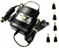
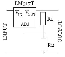
Can someone out there in electricland tell me how to make a permanent circuit that drops the voltage from 12 VDC to 9 VDC? I know that radio shack has multiple voltage power supplies etc. but I would like to make one of my own that's simple and only provides the 9 VDC without a bunch of extra stuff. I want to permanently mount it. This will be used to power an amplified TV antenna only. Thanks, Ron
-

4123 - The 300 Club
- Posts: 340
- Images: 50
- Joined: Thu Dec 13, 2007 11:54 pm
- Location: Cave Junction Oregon
Re: 12 Volt DC to 9 Volt DC?
![]() by starleen2 » Sun May 17, 2009 8:00 pm
by starleen2 » Sun May 17, 2009 8:00 pm
4123 wrote:Can someone out there in electricland tell me how to make a permanent circuit that drops the voltage from 12 VDC to 9 VDC? I know that radio shack has multiple voltage power supplies etc. but I would like to make one of my own that's simple and only provides the 9 VDC without a bunch of extra stuff. I want to permanently mount it. This will be used to power an amplified TV antenna only. Thanks, Ron
Look for the power adapter on the antenna and give us the required amperage for the antenna - also where is your 12 volt power coming from? a converter, battery, or something else? Dropping voltage is one thing, but knowing the amps would be useful as well
-

starleen2 - 5th Teardrop Club
- Posts: 16272
- Images: 224
- Joined: Sat May 12, 2007 8:26 pm
- Location: Pea Ridge ,AR