Australian "Cooroibah" Build update 19th dec 2009

...ask your questions in the appropriate forums BUT document your build here...preferably in a single thread...dates for updates, are appreciated....

Postby 2fry » Fri Dec 04, 2009 12:53 pm

I've updated my album.
Thanks for your comments. :)
User avatar
2fry
Teardrop Builder
 
Posts: 45
Joined: Sat Jun 13, 2009 9:14 am
Location: Sunny Scotland

Postby bve » Fri Dec 04, 2009 7:40 pm

Holy build updates Batman! ...I mean Irondance.

Nice looking build and yes great detail.

Classic Finn wrote:I dont want to hijack this thread but your tear is awesome looking too there Scotland Anymore pics of it?

Well said, Scotland we aren't seeing your album icon.
Burke

KISS > COMPLEX
Image
Image

Build threads converted to PDFs.
As of 2008-08-08 I have added more build threads to the pdf collection
User avatar
bve
500 Club
 
Posts: 694
Images: 98
Joined: Sat Aug 25, 2007 1:44 am
Location: Edmonton, Alberta, Canada

1001 things - a few

Postby irondance2003 » Sat Dec 05, 2009 1:59 am

Today is Saturday
Got up late (9am) No hangover (I don't drink) and decided that the day had come to do my most hated job plus a few that need to be done.
So first off I repainted the mudguards (this had to be done cause in a hurry yesterday I picked them up and they were still wet !!!! DAM***BUGGER.
then I went and did some more on the numberplate
And I just realised that I have not started the Number plate/Spare wheel holder-in -er POST.
THE NUMBER PLATE HOLDER.
At the back of the TD is the spare wheel holder and the section that will hold the spare wheel in will also hold the Number Plate and the light for it.
So I measure up the size of the hole and if you are following this build than your size will most liky be different so no sizes are done.
Image
Than I got a section of tin sheet.
Image
drew up the measurements and cut it out, you will notice that the top is larger than the bottom so I ran some gentle curves on the four corners.
Image
Than try it for a fit.
Image
So out with the Jenny and put some nice lines on it.
Image
Image
I than ran some other lines just inside the outer line(jump up) The reason was that the lines add strength to a very flexable bit of tin.
Image
I never ran these 2nd set of lines around the corner's.
I then cut 2 sections of 1in x 1in tube (25mm x 25mm) and welded them to the back about 4in (100mm) in from the ends.
Image
NOTE when you weld thick to thin like this lay the thin on a steel plate , start the weld on the thick and than just run the weld over till it touches the thin than stop.
The steel plate will take most of the heat and stop you blowing holes in the thin section.
Turn it over and if you have small sections of weld that show on the other side you have welded it if there is no marks on the other side repeat the welding untill you do.
Then run the grinder over the marks and flatten them.
Image
Clean it up give it a coat of primer and than paint.
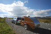
HERE IS THAT MORRY (blue)
Image
So mine is painted blue.
OK we are back to today..........
Today I mounted the Number plate holder.
First off I put it in place and then marked the floor just inside the rear chassis "x" member (don't drill the"x" member )in line with the 2 sections of the tube on the back of the NPH so the rods go down through these holes and tubes to the bottom holes.
Image
I then placed the NPH (Number plate holder) in place and marked the holes in the wheel holder where the threaded rod hit it .
I use threaded rod here as gravity and friction are going to be used to hold the NPH in place.
Image
When i have the holes in the bottom plate I cut the rods to just a bit above the kitchen floor.
I then got a section of flat strip steel and drilled 2 holes in it so that the rod pokes through.
Image
Image
Then get some wet newspaper and place it over the rods and put the flat steel back on and tack weld in place (the wet paper stops the floor burning)
Image
Pull this whole out and fully weld on the top at a higher amperage on the welder (we are only welding at the top and you need the weld to penertrate down the side of the drill hole along the rod, the rod is NOT welded on the backside)
Image
I also ran a tube of steel 3/8th's in (4mm) from the center to the side of the NPH at the top to run the wires from the light through.
Image
Yes I know I took the photo after the paint job.
Now clean up the weld with the grinder and give it a coat of primer and then paint.
When dry put it back in the holes with the NPH in place and you have it done.
The steel section that the rods are welded to hold it all in place and there is no way that it can vibrate out.
Today I added an old Number plate and the light so I could run the wires and put it all in place.
Image
Image
Image
Then I put on the Rear Bumper
Image
I will post this now.
And start another post re the rest of today.
Build with CARE, TIME will tell.OH and I changed my website in dec07
User avatar
irondance2003
Teardrop Master
 
Posts: 130
Images: 24
Joined: Mon Jan 30, 2006 1:26 am
Location: Noosa Queensland OZ
Top

MORE of Saturday

Postby irondance2003 » Sat Dec 05, 2009 2:25 am

OK the next bit is the
Image
DOG OF A JOB
On the underside of this build there is a fair bit of plywood sides that overhang the chassis rails so I had to jack up the TD put it on car props and get it high enough to get on a trolly and get under it and put a good layer of underbody deadner (black ,sticky, thick, anti chip,gunk that falls all over you when you are under it) and is a bugger to get off the outside of the finished Td when you do the edge at the bottom of the walls.
Image
then another section where the mudguards will be (this is just a first coat here as more will be done after the guards are put on.
Image
OK that was the day now I have to go and mow the lawn.
Build with CARE, TIME will tell.OH and I changed my website in dec07
User avatar
irondance2003
Teardrop Master
 
Posts: 130
Images: 24
Joined: Mon Jan 30, 2006 1:26 am
Location: Noosa Queensland OZ
Top

768 and one things left

Postby irondance2003 » Sat Dec 05, 2009 8:54 am

Another little post detail.
When the house kitchen was done a few weeks back I did the phone holder myself.
Image

So as part of not having large bits of wood to make the shelves I decided to hold them up with a fine alloy tube about 3/8th's in (6mm) this was just run through a matching hole size and a fine nail was put through the tube in the middle of the shelf (pre drill alloy)the curve at the bottom of the photo in the alloy tubes is that they are run down into the main backboard at about 35 degrees, I just predrilled some wood blocks then cut them on the bandsaw at 30deg and clamped them in place and run the drill back through the hole in the blocks and into th eback board.
Now on the TD when the poker work was done
Image
The future owner decided that he did not want the shelf all the way across as someone would put a sauce bottle or something on the shelf and hide the Art work.
So instead of 1 shelf we have 4 smaller shelves with the alloy used to hold them up same as the big kitchen.
Image
Image
The shelves are about 5in (125mm) wide and about that long, That being what I felt was a good looking length = about 2/3rds of total (counting both shelves on either side of middle).
OK thats up to date we will be back at a later date to fix the fridge ,Battery and the water storage.
Build with CARE, TIME will tell.OH and I changed my website in dec07
User avatar
irondance2003
Teardrop Master
 
Posts: 130
Images: 24
Joined: Mon Jan 30, 2006 1:26 am
Location: Noosa Queensland OZ
Top

A drawing

Postby irondance2003 » Sat Dec 05, 2009 10:01 pm

If you have a CAD program, Like the future owner of this beast than if you were playing around while waiting for the build you might do this.
Image

He did!!!!
Poor old Kel is champing at the bit to get his new TOY.
Oh and he is reading every bit of this as well.
Hang in there mate we are almost done.!!!!
Build with CARE, TIME will tell.OH and I changed my website in dec07
User avatar
irondance2003
Teardrop Master
 
Posts: 130
Images: 24
Joined: Mon Jan 30, 2006 1:26 am
Location: Noosa Queensland OZ
Top

Wheel Guards

Postby irondance2003 » Sat Dec 05, 2009 10:30 pm

Now the mud guards for this build are a Boat trailer builders spun steel job,
They toss a bit of steel in a machine with a drum in it and add some sheet steel and turn it on and run.
It is just a bit bigger than the size that it is spun on so I need to pull it into the shape I want plus mount it on the side of the TD.
Image
So first off get some mud guard washers (biggish washer with a 3/8th's in (6mm) hole.
Then put the guard on the bench.
Image
Now on each guard I am going to put 7 washers (just watch that you don't put them where the chassis is.
Image
So how do I work out where the chassis will be READ ON.
First off I inflated the tires to about 40psi then I cut 3 x 2in (50mm) blocks of wood the first was placed on top of the tyre and the next was placed at the front of the tire and I clamped these two blocks and the guards in place.
Image
Image
Then I clamped the 3rd block at the rear of the tire.
Image
Now on the inside of the guard you can draw where the chassis is.
DON'T JUST TRANSFER TO THE OTHER GUARD do the clamp bit again on the other side just in case .
If they match that is good (if they don't !!!! I won't tell anybody so you are safe)
Image
OK so the set up of the washers was for me 1 at the front and the rear about 1in (25mm) up from the bottom of the side wall and then above the chassis rail 5 washers spaced out as close to even as possible .
I then welded the washers about 1/4in (6mm) up the side of the inside of the guard with the other side of the washer sitting on the bench,
this means that when they are bolted in place there will be a slight pull on the washers at the center.
When you have them all welded in place flip the guards over and weld the other side as well...see photo above.
Now give them a clean and in my case run a grinder all over the surface.
Note I want a rough surface as I am not going for a Hi gloss finish on the paint work.
Now when clean just give a coat of primer and then as many coats pf paint you may require to get your desired look.
Me, I ground them rough then primed them.
Image
then primed
Image
Oh No Back soon
Build with CARE, TIME will tell.OH and I changed my website in dec07
User avatar
irondance2003
Teardrop Master
 
Posts: 130
Images: 24
Joined: Mon Jan 30, 2006 1:26 am
Location: Noosa Queensland OZ
Top

Back

Postby irondance2003 » Sun Dec 06, 2009 1:21 am

Even though it is the weekend (Sunday) folk just drop in.
Now back to the Mud guards...
My guards are not a nice shinny thing.
I do the underbody deadener inside the guards and on the outside using a Shultz Gun at high air pressure.
Image
This gives a dappled coat that is stone chip and dust and dirt resistant and will not show all the sticky little fingerprints.
Image
Image
Then some mid blue
Image
Just spray it on (i like to put a layer of the finish coat on the deadener asap but it will take a lot longer to dry with the enamel coat over it).
The deadner needs a week to dry before any more paint is put on.
I painted my Truck with this stuff and the paint over the top (yellow and grey) lasted about 4 years before I rebuilt it and the job done was as fresh as the day it cured even then and no stone chips where as the new Toyota Corrolla 18mts is chipped to hell.
That Truck is on the web site so have a look.
http://www.tjcampton.com
and the rebuild the back of the cab was done the same.
Back to subject.
Before the paint was applied to the guards they were reclamped to the wheels and the washers were marked so that I could drill the holes for the guards to be mounted.
Image
So at this point I am waiting till tomorrow to let them dry out and will mount them then.Stay tuned.
Build with CARE, TIME will tell.OH and I changed my website in dec07
User avatar
irondance2003
Teardrop Master
 
Posts: 130
Images: 24
Joined: Mon Jan 30, 2006 1:26 am
Location: Noosa Queensland OZ
Top

sunday 6th Dec

Postby irondance2003 » Sun Dec 06, 2009 6:15 am

Back again.
Now with the guards, if they are painted and you have the holes drilled into the side walls then there is not much that will stop you doing this.
Get your bolts that wll hold the guard on and place them through the walls on the inside and under the chassis on the outside.
Image
then place the guard onto the bolts and just start the thread on each bolt with a washer up against the welded washer.
Image
Image
Now you want the guard very lose for a bit about 1/4 in (6mm) gap between it and the wall.
Image
This is so you can get a bit of this stuff (it is a plastic strip with a hollow tube on one side of it) don't know the name but it makes a fine join between the guard and the wall.
Image
Then giving yourself at least 1in (25mm) overhang at the front start putting it between the guard and wall when you get to a bolt do this .
Image
yep just cut it enough to skirt the bolt .
Keep going untill you have it all the way round then tighten up the bolts (just watch that the tube section sits just above the join area.
Image
Now go around the other side and do the other (I'll do that tomorrow)
Image
Now that is the last post 4 today REAL-ie
Build with CARE, TIME will tell.OH and I changed my website in dec07
User avatar
irondance2003
Teardrop Master
 
Posts: 130
Images: 24
Joined: Mon Jan 30, 2006 1:26 am
Location: Noosa Queensland OZ
Top

other side

Postby irondance2003 » Sun Dec 06, 2009 11:06 pm

Just a short post .
When you do the other mud guard -
MAKE SURE YOU LET YA TIRES DOWN TO Normal pressure.
like I said short post
Build with CARE, TIME will tell.OH and I changed my website in dec07
User avatar
irondance2003
Teardrop Master
 
Posts: 130
Images: 24
Joined: Mon Jan 30, 2006 1:26 am
Location: Noosa Queensland OZ
Top

Paint

Postby irondance2003 » Mon Dec 07, 2009 1:11 am

Now what has not been talked about with much detail is the finish on this TD.
My system is very simple .
Shellac for a base coat (all got 2 coats) and in some places mainly the frame on the outer walls 4 coats.
This was then covered with 2 coats of water based clear (I used a good quality decking clear) I used a brush at all times (running with the grain) you can spray but with all the small amounts and bits that were painted a different times I would have spent half the build cleaning the spray gun so I just leave the brush in the paint and it is quick to do a section and even quicker to toss the brush back in the tin and hammer on the lid. (only clean up is for me)
And it all looks like this.
Image
Image
Image
You can get a deeper shine with more coats of clear (but you will get sick of the sight of glasspaper by the end of it)
So that is it for my finish (just every bit as it was fitted was Shellac-ed.
Build with CARE, TIME will tell.OH and I changed my website in dec07
User avatar
irondance2003
Teardrop Master
 
Posts: 130
Images: 24
Joined: Mon Jan 30, 2006 1:26 am
Location: Noosa Queensland OZ
Top

7th dec again

Postby irondance2003 » Mon Dec 07, 2009 1:44 am

Another subject that has not been posted is the sleeping section.
So here goes.
Again what is on the inside is very much up to your needs.
This one has room for the bed (duh) and a cupboard above the foot section (kitchen end) below this is a fold down shelf (somewhere to put the computer so as to watch movies on the laptop while it is raining) and 2 small book racks on either side of the fold down.
The wallet and watch shelf that was detailed a while ago (before the roof went on).
It all looks like this.
Image
That's the shelf folded up,
Image
And folded down.
The book racks are at either end of that,
Image
And as you can see as of this day NOT FINISHED. (yet)
You will note there is a 4in (100mm) flat section at the back of the fold up shelf, this is the section of the kitchen bench that was leftover after the speaker wall was put in and I have a reason for that and if you promice not to tell anybody I will let you in on the secret .
There is going to be a false wall put in here so that if you are camping and want to go for a walk or swim and want some stuff out of sight for even the most busy thief if they break in all they will see is the back of the kitchen wall.
Image
something like that
OK ...just remember TELL NO ONE!!!!!!
And if there are any naughty folk reading this ! Just you remember Australia is a big country and you will die before you even find this TD that alone the secret hide-ie-hole. Hehehehe
Build with CARE, TIME will tell.OH and I changed my website in dec07
User avatar
irondance2003
Teardrop Master
 
Posts: 130
Images: 24
Joined: Mon Jan 30, 2006 1:26 am
Location: Noosa Queensland OZ
Top

Tue 15th December 2009

Postby irondance2003 » Tue Dec 15, 2009 7:59 am

Catch up time.
Hehehe
Just remembered a Joke.
2 full grown Tomato's were walking down the road with there small child and the young tomato was going very slow and the father Tomato keep's yelling at him to go faster, but too no avail.
So the father gets very angry and go's back to the young one and smacks him in the head and the little fellow falls down and smashes all over the pavement, and the father say's KETCHUP.

OK I don't make a living from warped comedy.

OK lets catch up.
Of the few hundred things left to do in the next 15 days make that 13 (next Tue and Wed am replacing the motor box and diff in the Morris)
some have been done or are on there way.
1 ,, The Mag wheels were 2nd hand and looked like this.
Image
I tried to just polish them but to no avail so I repainted them and then hit them with 360grit wet and dry paper then the polish and after about 6 hours I had this.
Image
That's better

2,, As this is a warts and all build you had better get this small learning curve.
The wonderful job I did on running the overhead wire through the frame between the 2 layers of ply has come back to haunt me!
When I was putting up the walls at the start of the build I did tread on the wire that was hanging from the side wall and pulled the wall over , no damage was done to the wall and I thought no more of it.
Well I had to think of it the other day as I tried to finish the circut and there was no power feed to the lights.
There was power at the board (I undid the screws and lowered the board to check) but where the wire passed the doorway (only place at this point of time it is exposed) there was no power to the board, Yep when I tripped on the wire I must have broken it somewhere in the wall DAM BUGGER ***
So now that the TD is almost finished there is no way I can rerun the wire in where it was.
So a new wire has been run along the top of the wall on the door side next to the ceiling.
Image
insert a new wire loom
Image
use a bit of hot melt glue to stretch the wire in place and then I ran some masking tape either side of the corner about 3/8th's in (10mm) and then ran a large bead of no more gaps and with a big wet thumb I got this after I pulled the masking tape off (this is done while the filler is still wet )
Image
I will sand it later when it is dry.
I then walked away from the electrics for the time being as it was getting on my Goat. (giving me the Shits).
It get's that way with some things and the best way for me to deal with it is to do something else or I will wreck it trying to fix it!!!!
So I put in the Side window instead.
Image
Image
Now the side wall is a small amount wider than the store bought windows so I will put in some plastic strips ,The same as the one used on the mudguards .
Image
The bead is on the inside of the cab as there is a flange on the window frame. (this bead will hide the exposed wall)
The plastic was just stapled into place after the hole was made larger to fit it in as well.
I then trimmed the excess on the outside of the wall.
Image
Dry fit the window NOW.
All OK? then run a bead of sealer around the window frame and put the window in place.
Image
Image
You may also have my problem at this point all the nice short screws that will not go all the way through the wall and show on the inside (we have not got yet) BUGGER
Another run to the shop!!!!!!!
Build with CARE, TIME will tell.OH and I changed my website in dec07
User avatar
irondance2003
Teardrop Master
 
Posts: 130
Images: 24
Joined: Mon Jan 30, 2006 1:26 am
Location: Noosa Queensland OZ
Top

More Ketchup

Postby irondance2003 » Tue Dec 15, 2009 8:18 am

OK the Um er
Hatch Holder Up'ers

One can't go through life using a lump of wood to hold up the Hatch so I made up 2 lengths of alloy "L" shaped struts.
The height was set for the hatch when the future owner (Kel) dropped in to see the progress so what you set as an opening for your hatch will dictate the length of the alloy sections.
Image
Sorry bad photo (it's a photo for another post) But it shows where the struts are.
One end of the struts is drilled for a screw to go through and the other end has a slot at an angle so that you lift the hatch, unhook the struts (1 at a time) and place them on the screw in the side wall (they slide down the slot and the slot stops them from coming out.
Image
they are held in place with an eye hook that has been opened up to form a hook that is taller than the width of the alloy section.
Image
Image
OK this is a set of very simple struts and if you want to get some of the modern car boot struts that's great but they are a bugger to work out where to put them, Simple easy and easy to replace if they ever bugger up.
Now you will need a small amount of extra woodwork as you will find that the bottom screw for the struts on the side wall will hit the hatch as it closes so just mark where they hit and carve out the small bit of the hatch side strut
***************Add photo here******** Take one soon!!!!
OH and it looks like this.
Image
Build with CARE, TIME will tell.OH and I changed my website in dec07
User avatar
irondance2003
Teardrop Master
 
Posts: 130
Images: 24
Joined: Mon Jan 30, 2006 1:26 am
Location: Noosa Queensland OZ
Top

More Catch up (THE DOOR)

Postby irondance2003 » Tue Dec 15, 2009 9:10 am

Today I started the door.
Image
It goes where this big hole is.
Now the first thing I did was to look at the width of the wall
Image
And I need to build a frame around this hole on the inside Of the hole (but not at the bottom, The reason is that the bottom of the door is lower than the floor and this will help with getting grit out of the cabin and also will help keep the water, (if any gets to the foam seal ) and running down it will go past the floor and when it gets to the bottom it can only go out.
So a frame is put around the inside of the hole.
Image
My wall is (16mm) about 6/8th's in thick so the section in this will be the same 16 x 16 x length of hole.
Image
The section of tape is the foam seal for the door and this was used to work out where the inside wall frame sections were to go.
The idea is that when you close the door it will lodge onto another frame that is holding a foam seal strip (in this case 1in (25mm) wide) then when the door handle is turned into the lock position the seal will be fully engaged.
Image
The frame that is in the cabin is as wide as the tape and then wide enough to screw onto the wall.
I did the two sides up to the hight of the tape placement then I put a top rail across the top ,All this was glued and screwed in place and the holes from the counter sunk screws were filled with filler.
Image
Image
All the sides of this frame in the cabin were routered to the same profile I have used right through the build, The top rail was also routed on the outer edge so that where your head goes in there is no sharp edges (not be carefull here as there is a start and a finish to this routed bit and it is not all the way across (OH NO)
Image
That is not where you stop when routing this in (the tape will cover this (I hope) and only you and me and the owner know of it) DON'T TELL ANYONE ELSE.
Now from the outside we should have this
Image
You will notice that the top cross section on the hole is smaller by about 1/2 that was to keep as much headroom as possible.
At the bottom we have this look at the moment.
Image
The bottom hole timber ends up the width of the floor lower (may have to cut the seal down a bit here )
Now we do the frame on the outside the same as the cabin side the sides are cut to the height of the opening and routed (as there is a hinge along here you may not want to rout where the hinge will go.
Now put on the top cross member ,glue and screw in place and when the glue has gone off take out the screws and rout the whole outside of this frame (looks better) then sand it down and replace the screws.
Image
Image
Image
Image
That's the frame.NOTE.... All the screws on the whole TD line up with each other at any section of the build it is a small detail but the whole looks like you the builder cared for the job and adds to a better finish that may never be noticed but YOU will know and that adds to your pride in a job done well.
THE DOOR
Now at this point check how square the door hole has not become?
Yep once again with all the best intentions I am out by that much.
How Much?
1/8th in (4mm) bottom left to top right
Not a lot but it is there although by the time I have given all the door a clearence in the frame it will be close enough to be not there.
So grab a section of the ply that made up the thicker section of your wall and get it to fit the hole with 1/8th in (4mm) spacers all the way around.
Image
Build with CARE, TIME will tell.OH and I changed my website in dec07
User avatar
irondance2003
Teardrop Master
 
Posts: 130
Images: 24
Joined: Mon Jan 30, 2006 1:26 am
Location: Noosa Queensland OZ
Top

PreviousNext

Return to Build Journals

Who is online

Users browsing this forum: No registered users and 5 guests