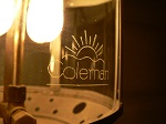
The casing look is a succes from an old 3/4 test Pine board.
Pretty impressive what some hole saw and some hand sanding can do...

Here's how I did.
Held the whole thing in a Vise.
I began by drilling the circonference with a 4" hole saw. (I kept 1/8" uncut in depth.
Then, I started with the biggest inner hole (2½"). Approx 3/16" depth. --> (To seat the PCB)
Next, I Used the 2" holesaw to an other 3/8" depth. (9/16" Total) --> (To Hold the Lexan). Leaves me approx 3/16" depth available.
Next, the center hole with a 1 3/4" --> (To let the light out...)
*After, You can clean easely the crap between stages with a flat screwdriver.
Finished the 4" hole (I started first) and started sanding...
I used some leftover 3/16" Lexan sheet from an other project and a old piece of Pine laying in my garage...
It looks awesome and its not even finished.....
I Also thought of venting em by doing 6x 1/8" holes on the side and by having a hole on center of PCB.

I'll Use 2x 1W Led (or 3) per puck. 3.3V @ 0.33A (160* view).
These can turn you blind if you look at em to close within the 160 degree Radius...

Heres my calculations for 2 Led/Puck (Led in series)
R = (VSource - Volt LED) / Amps LED
R = (12.6V - 6.6V) / 0.33A = 18.18Ω
PRes = (6V * 0.33) = 1.98W
(4x 72Ω 1/2W in parallel.)
Heres my calculations for 3 Led/Puck (Led in series)
R = (VSource - Volt LED) / Amps LED
R = (12.6V - 9.9V) / 0.33A = 8.18Ω
PRes = (2.7V * 0.33) = 0.891W
(2x 16Ω 1/2W in parallel.)
OR
Connecting 2x (2 Led) Puck Lights in Series to Eliminate the useless Heating and
power eating resistor in the circuit.
EMAX LED = 3.3V x (2 x 2 Led) = 13.6V
In Theory the Puck lights would be near optimal brightness, will have less heat dissipation if
the car alternator is charging and they will have a longer life....
I think it's the best solution but 3 led looks better than a 2 leds puck IMHO...
Will test and post the results...
I have an Idea, but dont have the thing on hand at home to confirm it.
I have access to Old LCD screen. In those, there is some back Reflective papers between the Backlight and the LCD itself. To be simple,
it gives the screen a uniform brightness. (So, you dont see the Blacklithing brigther on top and bottom than in the middle of the screen)
With those, the light wont pass if not within a certain angle. So i could make the led more like a "Cool" lightning...

And, we wont see the PCB and the leds at all...

I cant wait to test that theory.


I started the top Cabinet.
Starting from the top:
On each side goes a 6" Speaker.
On center im undecided if i leave it open of with a big or 2 small doors. (No worry, i can think about this later....)
In the middle, 2 small cabinet. between em goes 2 embeded 3" Can Holder, a 120V (For eventual alarm clock) and 12V Outlets and 2 (or 3) Puck Lights
On the Bottom (Not builded yet), will be 2 big cabinet. strong enough to support us when we will lean back against it to watch TV. I have no Idea yet how I will do it...
Also, I'll need to finish the floor and roof there before going any further with the bottom Cabs.

You can notice one of the future 3" Embeded glass Holder.
At the time to take these photo, only 4 screw were in place to hold all this... (No j/k..)
On this pic, Everything is holding by my prayer....