Sidewall graphic help

Anything to do with mechanical, construction etc

Sidewall graphic help

Postby Larry C » Sat Oct 08, 2011 9:12 am

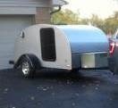
I am designing the graphics I want to inlay with wood strips into the plywood sides of the Mike's Ultralight profile. I would like to do something similar to the photo below which belongs to another member. I hope he doesn't mind me using his great example.
I don't have a clue how to go about getting such a design onto the Ultralight profile.
I would like to get it onto the profile with xy points so I can use a batten to get the curves and make a template so I can cut out the graphic (white area) and fill back in with wood strips.
Can anyone help me with this problem?

Thanks,
Larry C

[img][img]http://i53.tinypic.com/drea02.png[/img][/img]
"If its worth doing it's worth doing Light"

http://www.tnttt.com/viewtopic.php?f=50&t=35852
Larry C
500 Club
 
Posts: 732
Images: 78
Joined: Sun Dec 27, 2009 9:37 am
Location: Finger Lakes

Postby Chef_Stan » Sat Oct 08, 2011 5:54 pm

since you alrady have the image you could put a grid over the image and scale it up to what you need, then make you template from there. It is old fashoned but it would get the job done quickly.

Stan
Chef_Stan
Teardrop Builder
 
Posts: 34
Joined: Sun Jun 19, 2011 8:42 pm
Location: Canterbury, CT

Postby Larry C » Sun Oct 09, 2011 9:10 am

Chef_Stan wrote:since you alrady have the image you could put a grid over the image and scale it up to what you need, then make you template from there. It is old fashoned but it would get the job done quickly.

Stan


Thanks, Stan I think I understand what you mean, but I am not sure how I would transfer it to the Ultralight profile. I had hoped there was a design program someone has that could easily put the graphics on the profile. maybe even Photoshop could do it. Like I said, I am clueless when it comes to creating designs.

Here is the link to the side profile I am using. I am just uing the profile, not the wall construction method.
http://www.mikenchell.com/TheUltralight.pdf

If I could get the graphic onto the Ultralight profile and have the xy grid plotted I could make it work from there.
Maybe I am going about this the wrong way, if so someone please steer me in the right direction.

Thanks,
Larry C

Image
"If its worth doing it's worth doing Light"

http://www.tnttt.com/viewtopic.php?f=50&t=35852
Larry C
500 Club
 
Posts: 732
Images: 78
Joined: Sun Dec 27, 2009 9:37 am
Location: Finger Lakes
Top

Postby Pizzaguy » Sun Oct 09, 2011 1:22 pm

Let me see if I can explain this simply......

1st off get Steve Fredericks Shop Manual available here.......

http://www.steve-frederick.com/shopman05.html

I kinda did what you wanna do, just not quite as complex.

Image

Left side is Cherry, right side is Birch.

I built a 5'X9' table to accomplish this on.....

Image

If you notice surrounding the table are blocks to act as stops. You'll notice that every other block is offset by about a 1/2" difference. This pic was taken right before I cut the 2nd half. (AFTER the 1st half) You'll also notice the pattern I used to cut it with a router. The KEY is that pattern NEVER moves once I start making the cuts. So to summarize I put the 1st sheet down, use the edge of the plywood to line up & screw down the stops. I then lay down the pattern to where I want it to be and secure it so it NEVER moves. I make the 1st cut w/ the router, remove the 1st sheet, put down the 2nd sheet offset by 1/2". Route out the 2nd half with the pattern in the same position..... (REMEMBER, it never moves) and I now have left & right halves that perfectly match and butt up to each other. the cuts are EXACTLY mirror images of each other!!

After laying down fibreglass mat & epoxy I have a sheet of plywood that looks like this.....

Image

After building my walls and the rest of the trailer it looks like this.....

Image

What you want to do might be a lot more complex but would be do-able.

Get Steves Shop Manual, it's all explained there. Take a look at his web page and you'll notice he's incorporated this technique in a bunch of his builds.

Bruce
Image
User avatar
Pizzaguy
Teardrop Master
 
Posts: 173
Joined: Mon Feb 02, 2009 8:32 pm
Location: Livin' Life On The Croix, Hudson WI
Top

Postby Larry C » Sun Oct 09, 2011 3:45 pm

Bruce, Nice job using Steve's method. I have always admired your build. I already have Steve's manual, and may incorporate the method to cut my plywood.
However, right now I am still trying get the design shape onto my profile so I can make a template. That is what still has me stumped. I had been hoping someone had a design program that could simply superimpose the graphic design onto the Ultralight profile, and give me xy points to plot the curves.
I am probably asking for something that doesn't exist.

Thanks for your description of the cut out method, I am sure it will be helpful if I ever get that far!

Larry
"If its worth doing it's worth doing Light"

http://www.tnttt.com/viewtopic.php?f=50&t=35852
Larry C
500 Club
 
Posts: 732
Images: 78
Joined: Sun Dec 27, 2009 9:37 am
Location: Finger Lakes
Top

Postby Shadow Catcher » Sun Oct 09, 2011 8:42 pm

Far simpler would be to use a custom wrap ours was done by http://www.badbrush.com/color_printing_wraps.htm
Ours was die cut.
Image
User avatar
Shadow Catcher
Donating Member
 
Posts: 6008
Images: 234
Joined: Sat Apr 11, 2009 8:26 pm
Location: Metamora, OH
Top

Postby Larry C » Mon Oct 10, 2011 7:04 am

Shadow Catcher wrote:Far simpler would be to use a custom wrap ours was done by http://www.badbrush.com/color_printing_wraps.htm
Ours was die cut.


Shadow Catcher:

Your right, vinyl or painted on would be a lot easier, but this will be a woody, and I want to do something a little different. The sides will be 4mm Okume plywood. The cut out graphic will be wood strips inlaid into these cut outs. Also, the sides will be glassed.
This will be hybrid construction using marine ply, and wood strips. Not sure how well it will work, but it will be different for sure.
"If its worth doing it's worth doing Light"

http://www.tnttt.com/viewtopic.php?f=50&t=35852
Larry C
500 Club
 
Posts: 732
Images: 78
Joined: Sun Dec 27, 2009 9:37 am
Location: Finger Lakes
Top

Postby DMcCam » Mon Oct 10, 2011 1:02 pm

Hi Larry, You might ask the member who's design you like if he would be able to help you. He would likely be a simple job to fit it to ultra light profile too.

Cheers,

Dave
User avatar
DMcCam
Gold Donating Member
 
Posts: 883
Joined: Wed Jan 06, 2010 8:30 pm
Location: Reno, Nevada
Top

Postby Larry C » Mon Oct 10, 2011 3:21 pm

DMcCam wrote:Hi Larry, You might ask the member who's design you like if he would be able to help you. He would likely be a simple job to fit it to ultra light profile too.

Cheers,

Dave


Dave,
I am not necessarily trying to copy the exact design. That's just an example I like. I am more interested in how one goes about inserting any existing design graphic on to a profile, and maybe be able to change it to suit my eye.

I was hoping there was a simple (free) design program that would allow me to take a known design and insert it onto my profile and be able to change it's length, width, add, subtract items, etc. I then would need to get my new design onto some type of template material.

Thanks for your suggestion....
Larry C
"If its worth doing it's worth doing Light"

http://www.tnttt.com/viewtopic.php?f=50&t=35852
Larry C
500 Club
 
Posts: 732
Images: 78
Joined: Sun Dec 27, 2009 9:37 am
Location: Finger Lakes
Top

Postby mallymal » Mon Oct 10, 2011 6:08 pm

Maybe I'm missing what your trying to do.... but try this....

I don't do Sketchup, so I've been playing with designs in Microsoft Publisher. If you dont have that, try plain old Microsoft Word...

1) create a new document with a page size of LETTER size (8" x 11"?) (I'm translating from English here!)
2) Make sure page is landscape
3) If you want a tear that is say 8' x 4', convert that into inches.... 96" x 48"
4) That will fit nicely on your page at 1/10th scale.... in other words it will be 9.6" x 4.8" on the page
5) Import your chosen image of the profile (Insert/picture command), and if need be drag the corner "handle" to scale it up or down..... hold down SHIFT while doing this to stop it distorting.
6) Now scale it.... to do this insert a RECTANGLE shape over the top of your profile. Double click the rectangle to edit it's properties.... make it's ssize exactly the size of your tear DIVIDED BY 10.... so that's 9.6" x 4.8" in our example
7) Also give the rectangle NO FILL but a line in a nice bright colour. This isnt part of the design, it's just a scaling tool
8)Now drag the corner handle of your tear profile to line up all round, so it looks like this...
[img]
https://picasaweb.google.com/purealgarv ... directlink[/img]

9) Then trawl the web for swooshes & graphicss you like and import them into your design.
10) When you come to scale it all up, its just x 10

Simple ;)
User avatar
mallymal
The 300 Club
 
Posts: 308
Images: 18
Joined: Fri Sep 26, 2008 4:20 am
Location: manchester, UK
Top

Postby Verna » Mon Oct 10, 2011 9:15 pm

Well, you could get really fancy and do a marquetry design:

Image

Or do a geometric parquetry design:

Image

You could use a router to cut the design into the wood, and use a jig saw or scrollsaw to saw the design to fit the routed areas.

Draw the design on cardboard that is the same size of your TD, figure out what gets routed out, what stays, what gets cut to be inlaid back into the TD wood.

Just some random thoughts.

Verna
Verna
Indianapolis, IN
User avatar
Verna
Gold Donating Member
 
Posts: 1407
Images: 49
Joined: Mon Aug 08, 2011 11:11 am
Location: Indianapolis, IN
Top

Postby DMcCam » Tue Oct 11, 2011 10:34 am

Hi Larry, you might look into Inkscape, it's a free open source vector drawing program available at inkscape.org. You just download it to your platform (pc or mac) and install it. There are tutorials, free clip-art and examples galore on the site. I hope this helps.

Cheers,

Dave
User avatar
DMcCam
Gold Donating Member
 
Posts: 883
Joined: Wed Jan 06, 2010 8:30 pm
Location: Reno, Nevada
Top

Postby chartle » Tue Oct 11, 2011 4:48 pm

DMcCam wrote:Hi Larry, you might look into Inkscape, it's a free open source vector drawing program available at inkscape.org. You just download it to your platform (pc or mac) and install it. There are tutorials, free clip-art and examples galore on the site. I hope this helps.

Cheers,

Dave


I was just about to post this.

I'm using Adobe Illustrator which is also a vector based program but its like $500. Inkscape is free and I tinkered around with it until I got AI (I use it at work) installed. I just create a full size plan and go from there.

Here what I have so far. (I can't take credit for the drawing of the HF trailer or the figures).

Image
chartle
Teardrop Master
 
Posts: 159
Images: 3
Joined: Thu Aug 18, 2011 8:30 pm
Location: Pgh
Top

Postby Pizzaguy » Wed Oct 12, 2011 12:40 am

Hey Larry,

Check out JuneauDave's build. I think he did what your trying to do.

http://sites.google.com/site/slumbermax/Home/stripping-the-sides
Image
User avatar
Pizzaguy
Teardrop Master
 
Posts: 173
Joined: Mon Feb 02, 2009 8:32 pm
Location: Livin' Life On The Croix, Hudson WI
Top

Postby Larry C » Wed Oct 12, 2011 6:56 am

Pizzaguy wrote:Hey Larry,

Check out JuneauDave's build. I think he did what your trying to do.

http://sites.google.com/site/slumbermax/Home/stripping-the-sides


Thanks Pizzaguy!
I am very familiar with JuneauDave's exqusite build. However, his is done completely in strips. I want to do a hybrid of mahogany plywood and strips. I have to cut out the plywood sections, and fill back in with strips.

Larry C
"If its worth doing it's worth doing Light"

http://www.tnttt.com/viewtopic.php?f=50&t=35852
Larry C
500 Club
 
Posts: 732
Images: 78
Joined: Sun Dec 27, 2009 9:37 am
Location: Finger Lakes
Top

Next

Return to Teardrop Construction Tips & Techniques

Who is online

Users browsing this forum: No registered users and 0 guests