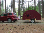
Saturday was overcast and dank. A bit chilly, too. When I arrived at the shop (Metal Werks, aka Fab Mecca) I was greeted warmly by this.
The guy with the saw mill and timber framing business that put up Karl's barn (A long time friend of Karl's and sometimes business collaborator) wants to build a drying tumbler for his wood chip mill that is powered and heated from his 200kw diesel gen, so we had arranged for me to give a tour of the CHP (Combined Heat and Power) plant that I helped build at my work. That was going to break up our day some, so we stuck to some smaller tasks.
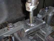
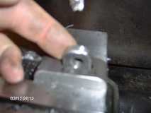
Just a few small things left to do before we can start on the frame assembly. The ID of the pintle sleeve in the little front tongue xmbr had been left under size until after the sleeve had been welded into the xmbr, so that needed to be sized for the bushings before going on the frame. Here we are at the mill using a cheap adjustable Chinese reamer.
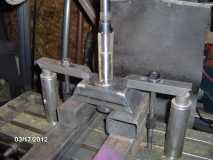
Note all the extra spacer blocks that were needed due to the long adjuster thread on the reamer.
We fiddled with that quite a bit, creeping towards the final dimension, not at all happy with how it was doing. Difficult to adjust with any accuracy, seemed to be cutting on less than all blades, chatter and flare at the top, and under size at the bottom.
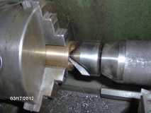
Switched to the boring bar before it was too late to fix. At the bottom left of the bar you can just see the back of the carbide cutting tip.
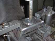
Here we are using the power feed on the mill's spindle, feeding the boring bar into the pintle sleeve as the spindle rotates the cutter. You can also see the adjustment head on the boring tool that lets you adjust the cutter bar in or out.
Came out dead on 1.500 when checked in two axes at both ends.
Because the pintle shaft has a moderately sized radius between the shaft surface and shoulder thrust face, the chamfer on the front bushing ID needed to be increased slightly. Here it is chucked gently in the lathe with a counter sinking cutter.
Here I am cutting a chunk of steel for the coupler removable pin locking block.
And here it is after cutting it in half again, and milling the slot for the lock tab into it (sorry for the blurry pic...the wife has suggested that I try using the camera zoom instead of putting the camera so close...I'll try that next time).
Here I am test fitting the lock tab in the slot before removing the block from the mill (to preserve the indexing in case the slot needed to be made bigger).
And here's a better pic of the block and tab together on the plan.
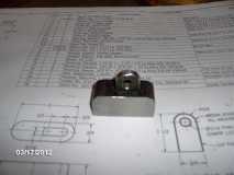
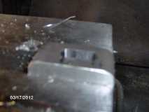
The block still needs to have the undercut made where the pin bolt head goes, and the corners need to be rounded off for aesthetics.
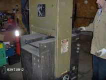
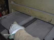
Here's Karl feeding a frame member thru the Time Saver (a big belt sander).
Stick the part in here...
Brush the metal dust off as it comes out here...
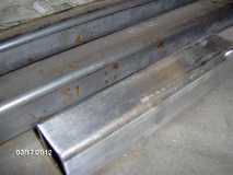
Flip it one side and stuff it thru again, wash rinse repeat, and here is a comparison of the result.
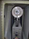
Here's a shot inside the cabinet. It's a fairly complex mechanism with air solenoids and a rocker set up that constantly tips the upper roller back and forth so that the belt is always tracking to one side or the other. That way the belt is always being controlled and can never run off the end of the rollers.
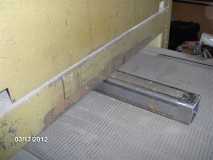
And here's a pile of shiny frame parts ready to go.
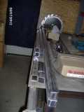
The big saw tooth looking thing in the background is Karl's tubing bender.
Be right back with Sunday's exploits! It's big.