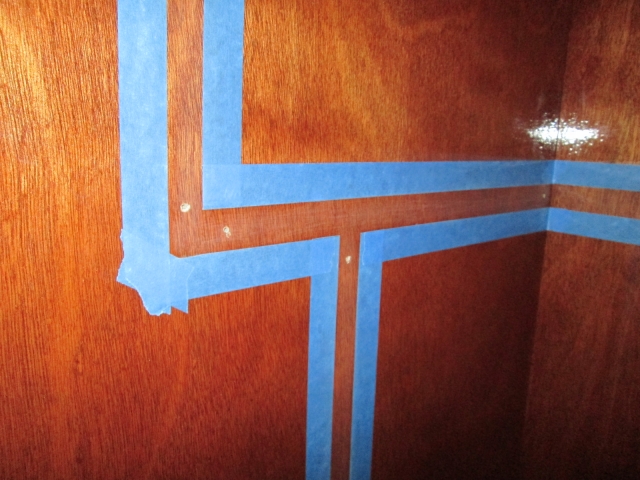
Time to get caught up on the miscellaneous stuff with pics. As mentioned, last Monday I scuffed the taped off areas on the walls at the rear of the cabin where the cabinet ledgers will get glued. Kind of hard to see here because I just used a greenie pad. I was concerned that if I got too aggressive with actual sandpaper, that I could start to cut into the tape and cause problems.
Next I applied stain to the two cabinet floor panels.
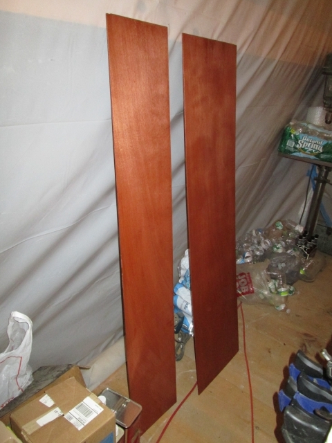
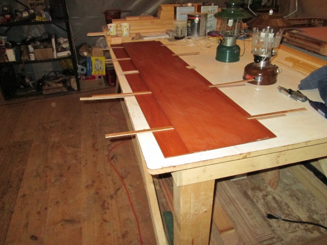
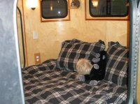
I was afraid that they might warp up if I left them leaning against the wall like this, but wanted to give them plenty of air for the stain to dry, so I stickered them with some scrap sticks of the ply and left them flat up off of the bench.
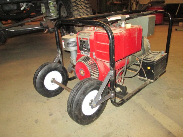
And now another distraction; the Winco 5500w generator (Genny). Eric had fit 2x3 into the bottom xmbrs to which he had screwed some small fixed casters (you can kind of see the wood in the first pic). That worked fine for him (allowing him to roll it out of his basement up a concrete ramp and onto the concrete pad under his dining room bump out), but I would need bigger wheels to allow me to wheel it on less even surfaces. At first I removed the little casters and screwed some 1 inch thk rubber vibration mounts in their place. Then I fabricated an axle and triangulated mounts using angle steel to support a pair of 10 inch wheels.
The idea was to make it like a two wheeled wheelbarrow where the wheels were set about 7/16 inch above the ground (the thickness of a 1/2 inch thk sheet of plywood used as a shim) when the Genny was sitting on the rubber mounts, and lifts up onto the wheels when the handles are used. I didn’t want to make it any wider than it was, so the big wheels went out the end. Well, before when you picked up each end it didn’t feel that heavy because the pivot point was part way underneath. Now when you pick up the other end the leverage point is way out front and it suddenly is not at all easy. Doh.
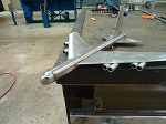
So I slept on that and came up with a plan to make it a trike using a 6 inch swivel caster on the other end. Removed the rubber feet and wood, set it on the wheels level and added the caster. Wished I had planned it that way from the beginning and was disappointed at the low ground clearance (only 3/4 inch). Slept on that again and decided to bite the bullet and raise it up another 2 inches.
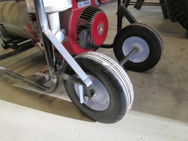
To do this at the (now) front, I used longer bolts and pipe sleeve spacers between the caster mounting plate and caster, and at the (now) rear I cut 1 inch wide windows where the axle thru holes had been and welded in new angle steel posts with new axle holes (on one end of the axle the hole is actually a slotted saddle, and the cotter pin does double duty keeping the axle from dropping out… gravity does the grunt work). In order to keep the wheels inboard, but as far out as possibly, yet keep the axle mount brackets in line with the chassis tubes, the axle is 3/4 inch dia (actually a little bigger) turned down on the ends to 5/8 dia for the wheel bearings. A couple of spacers made out of 1/2 nominal black pipe (.632 id) between the wheel bearings and axle brackets keep the wheels from sliding over and hitting the brackets. The axle shaft is cross drilled 1/8 inch at each end outside of the brackets where cotter pins retain it.
Here is the revised and raised rear suspension.
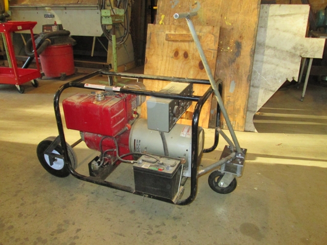
And an overall shot showing the front caster mount with lift spacers and T-bar draw handle.
It pulls across uneven ground very well now, but can be a little tippy on side hills (due to length vs. width on 3 wheels). However, it is still low enough that the corner of the frame hits ground first before it would tip over, so no harm.
Used the tilt feature on The Briq to get it home tonight (Note to self: if you want to turn the load around before strapping it down, pin the deck back down first, elsewise the deck will tilt again and the load will run right back off the end). Now I just need to make up a cord and make a level pad under the porch… in due time.


 So you’re just minding it , making sure it stays in top working condition for the team ... eh ?
