For our anniversary Yvette got me a healthy gift card from the big orange box. I probably should have waited and seen if there was any more materials that I will need for the camper (exterior paint comes to mind now that I think about it), but another thread put it in my mind that I might get a discount on tools because Father’s Day is coming up (even tho I am not a father). So basically, I decided to spoil myself a little and splurge on a tool that I probably don’t need, but that I will probably use and enjoy, and should come in handy.
This trim router.
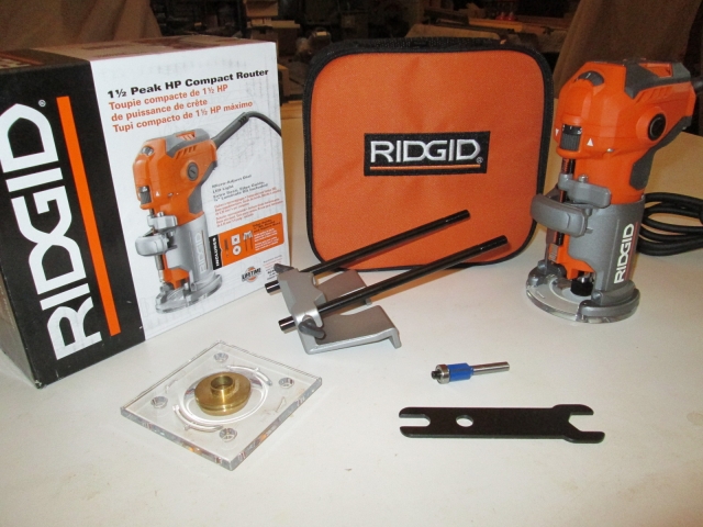
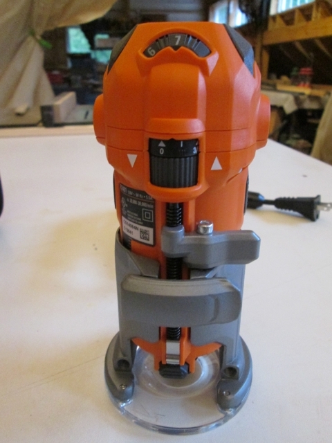
They had the Makita model as well (in the box under the display, but not on display; probably last year’s leftover stock). It was appealing because it had an aluminum motor housing (where the Rigid’s is plastic), and was $10 less, but it didn’t have as many features, didn’t have the LED light, and I didn’t like the depth adjusting mechanism as much (hard to release and sloppy backlash). The specs said the variable speed on the Makita was from 10k to 30k rpm, whereas the Rigid was from 20k to 30k, but when I tested the Rigid it sure seemed to me like the speed went plenty low enough.
The Rigid came with a soft case; both round and square clear plastic bases that key into a concentric alignment feature and accept my standard guide bushings (as demonstrated on the square base in the pic); a guide fence w/ rods; a short 1/2 inch bottom bearing flush cutter; the collet wrench; and the aforementioned LED light. The on/off switch is on top and lifts up for ‘on’, and pushes down for ‘off’, which seems very ergonomic to me. The depth adjustment toggle clamp seems positive, yet is easy to operate, and the fine adjust thread has a quick release lever that makes coarse adjustments very easy; both of which seemed better than the Makita. I’m looking forward to having an excuse to use it!
So the rest of tonight was working toward getting set up to do the final install of the front wall assembly. Time to test some PL Premium glue between scraps of blue foam and 5 mm ply. Mostly I’m looking to develop a technique that reduces or eliminates squeeze out, but makes a solid joint at all of the critical junctions. The PL is a good choice for the structural joints between the toe kick spar, locker base and floor, as well as where the front skin meets the side wall edges because these areas all have small irregularities in the fit. However, the PL must be cleaned up with mineral spirits before it starts to kick very much, and I have to believe that quite a bit of time is going to pass as I lay the glue down, get the wall in place, screwed down and clamped before I have a chance to chase the squeeze out.
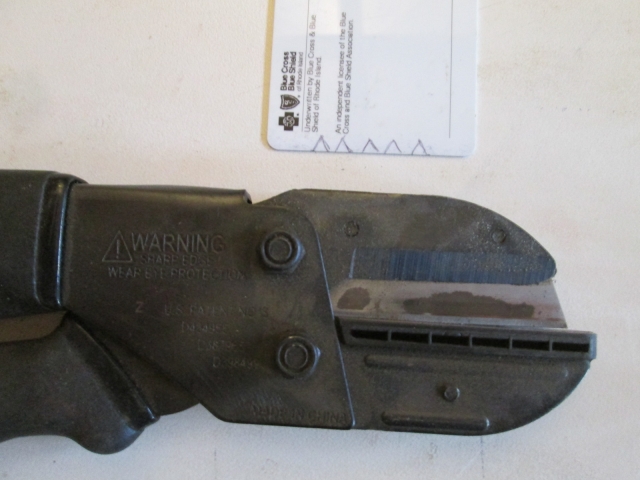
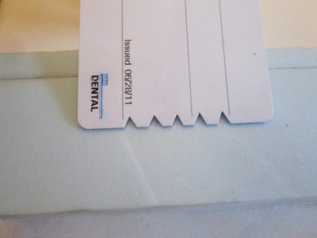
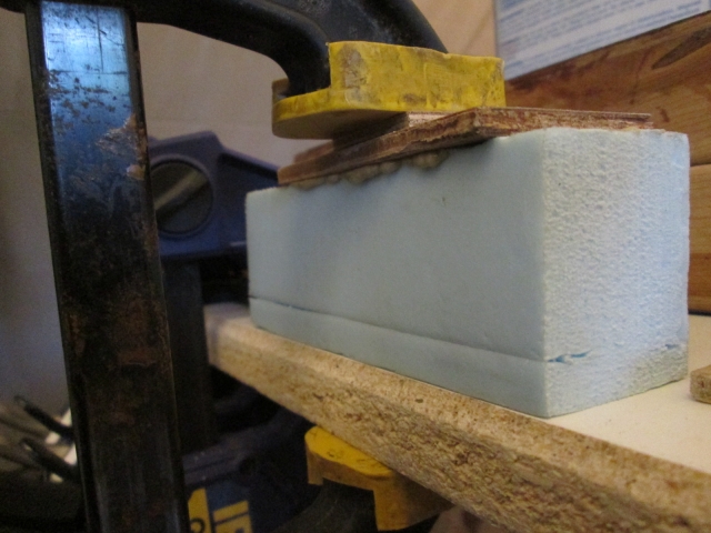
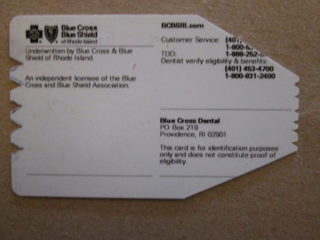
So my thinking is to use a notched applicator and limit where I spread the glue so that it’s not too close to any of the inside surfaces. The front wall skin overlaps the sides by about 1-3/16 inch and the toe kick spar is 1-1/2 inches, so Test #1 was to make a 1/8 inch notch spreader. I figured that if I put the notches only in the center inch or so of the spreader, the outside edges would wipe the excess off. So here’s the first layout shown with the “Bob Villa Cutters” that I used to cut the notches.
It spread the glue pretty nicely, too…
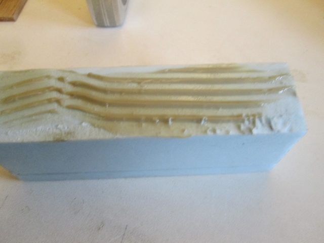
… but by the time the parts were done sliding around there was quite a bit of squeeze out.
I did a second test with smaller notches in a narrower pattern, but the outer portions seemed to bulldoze the excess glue further out to the sides than I wanted, so I trimmed those back at an angle (to help keep some of the stiffness in the card) and it worked much better; giving me the control to put the glue where I wanted it, and the squeeze out was greatly reduced. I might do another test with a larger notch near the center for a positive bead, but keep the smaller notches near the outside edges.
Also, I might use TB2 on the shelf and cabinet ledgers (which can easily be made nice and tight), instead of the PL, but still use the PL around the perimeter and base.
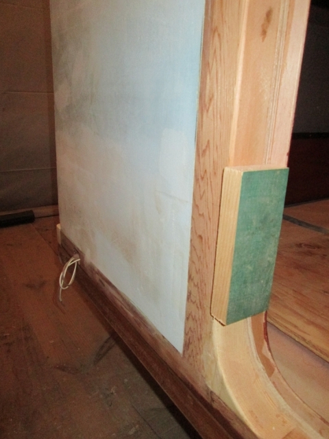
Next I stapled some spacers onto a couple of lengths of 2x4’s to act as strong backs for gluing the front skin edges to the walls without screws. The space will allow me to insert wedged shims and control the amount of squeeze (clamping pressure) everywhere along the 2x's.
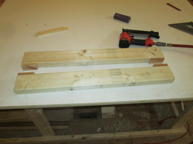
Later I used a piece of double sided tape stuck on the top spacer to hold the strong back in place so there wasn’t so much juggling to get the bar clamps in place.
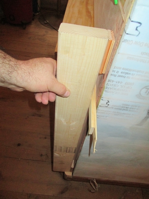
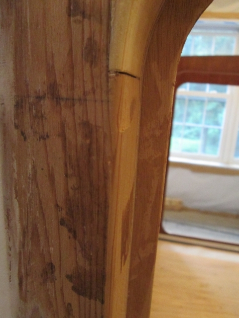
At the door jamb side, on a previous clamp job the clamp made a dent in the soft cedar (just visible here below the gap that needs filling at the radius joint)…
… so to prevent that from happening again I used double sided tape to temporarily hold these clamp blocks in place.
And here’s the complete mock-up of the clamp job.
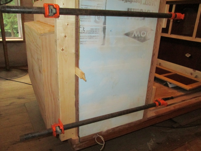
This clamp setup will go on after the screws are run into the bottom of the locker, the toe kick, the joins at the side wall where I can put screws, and along the shelf ledgers. This is going to be a serious glue up with a lot going on all at the same time, which is why I want this all sorted out before I start spreading glue everywhere. I want to be sure it goes well!
I will probably do another full walk thru, and may even pilot drill and run all of the little screws in once before applying the glue.
Next I climbed inside to look closer at that end of things. I decided that the masking job would be extensive, and not easy due to all of the different things going on and the interaction of the joints, plus gravity, so it reconfirmed my efforts to minimize squeeze out. While there I marked along the base of the front where the masking on the floor would need to be trimmed (or redone).
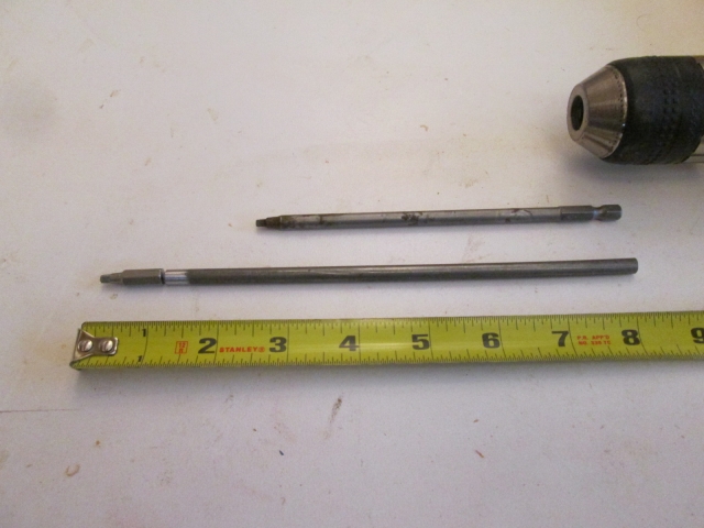
Next I decided to make sure that I can drive the Kregg screws down thru the toe kick in the locker well. Good thing I checked. The chuck of the drill would have hit the sill, and I couldn’t tip the drill far enough to get an angle on it before the back of the drill hit the inside of the locker. I could put the long Kregg square driver bit into my 6-way driver tool and, in theory, hand drive the screws, but it was questionable with the small space and the self-tapping screws not being pilot drilled into the floor (the pilot holes were only drilled into the toe kick).
So I measured what it would take to get the drill up higher into the opening of the locker using a longer driver that would pass by the sill, and came up with this (shown next to the standard Kregg bit). I cut a piece of 1/4 inch pencil rod and will weld the short square drive bit onto the end, perhaps tomorrow.