
Teardrops n Tiny Travel Trailersor t n ttt for short (tnttt.com) |
The Poet Creek Express - Foamie Hybrid
Moderator: eaglesdare
Re: The Poet Creek Express - Foamie Hybrid
![]() by KCStudly » Sat Nov 29, 2014 7:40 pm
by KCStudly » Sat Nov 29, 2014 7:40 pm
Thanks Chas, and welcome to my madness.
KC
My Build: The Poet Creek Express Hybrid Foamie
Poet Creek Or Bust
Engineering the TLAR way - "That Looks About Right"
TnTTT ORIGINAL 200A LANTERN CLUB = "The 200A Gang"
Green Lantern Corpsmen
My Build: The Poet Creek Express Hybrid Foamie
Poet Creek Or Bust
Engineering the TLAR way - "That Looks About Right"
TnTTT ORIGINAL 200A LANTERN CLUB = "The 200A Gang"
Green Lantern Corpsmen
-

KCStudly - Donating Member
- Posts: 9640
- Images: 8169
- Joined: Mon Feb 06, 2012 10:18 pm
- Location: Southeastern CT, USA
Re: The Poet Creek Express - Foamie Hybrid
![]() by KCStudly » Sat Nov 29, 2014 11:59 pm
by KCStudly » Sat Nov 29, 2014 11:59 pm
Taking a close look at the Marinco 15A battery charger connection it had two options for mounting thru what I am now calling the “power bulkhead”. The shaft of the housing had molded threads with a large gland nut like most electrical connectors, or you could use the three provided screws through the holes in the flange. I preferred the screws for several reasons: the nut could loosen allowing the connector to spin; the power bulkhead is 3/4 inch thick and I would have to counterbore the back of it to suit the short length of the threads, whereas with the screws all I needed was a clean hole; and I would want to fill the screw holes anyway, rather than leave them exposed and empty. Now, the thing is that the screw holes were practically on top of the threads. If I had just cut the hole to the size that it would take for the threads to fit thru, the screws would be busting out thru the edge of the hole. So I sanded the threads off using the Bader and cleaned it up some with the hand block. This would allow me to make the thru hole smaller and leave a little extra margin for the screws.
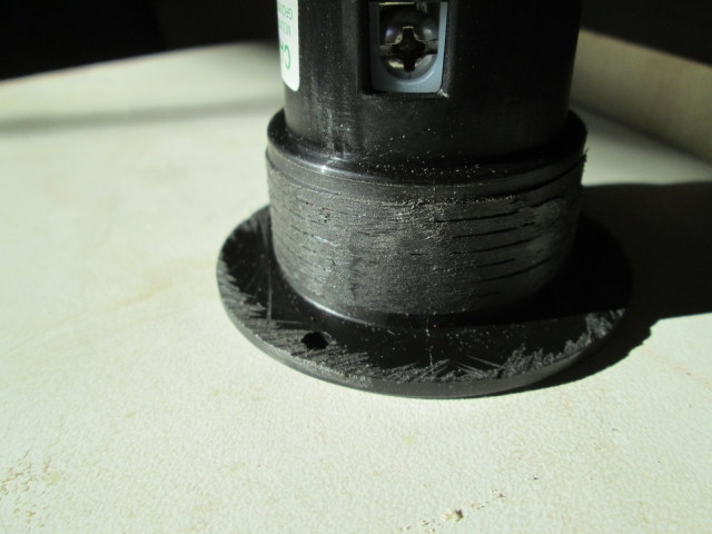
It scuffed the back of the flange up a little, but the gasket that is part of the rubber cap lanyard will handle this easily.
Rather than doing a setup on the mill, I decided to just cut the hole with the little jig saw. Laid the pattern out, drilled a pilot hole, threaded the blade and cut it out.
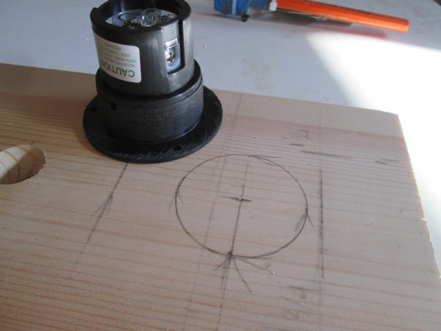
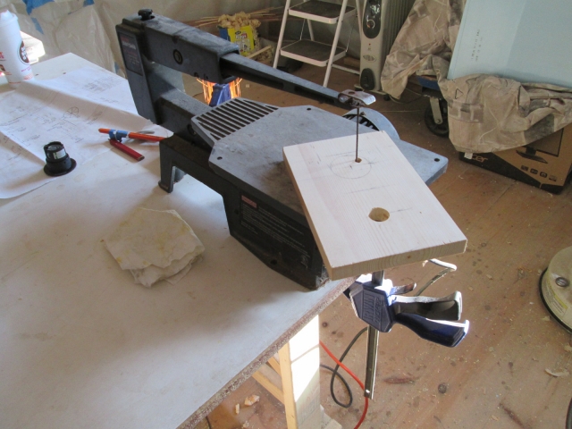
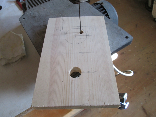
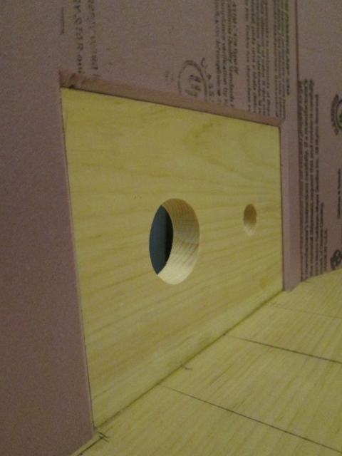
You can also see that I had already drilled the smaller hole for the Perko connector for the solar panel connection.
Unfortunately, the larger hole came out bigger than I wanted resulting in a sloppy fit and less margin for the screws. So I made the piece over again. This time the hole was a little too small. It was a little more off than what I could sand out easily, but not enough to make another cut on the saw; so I used the same technique to make a 5mm thk router template, just a little bigger, and opened up the thicker material using the flush cutting bit.
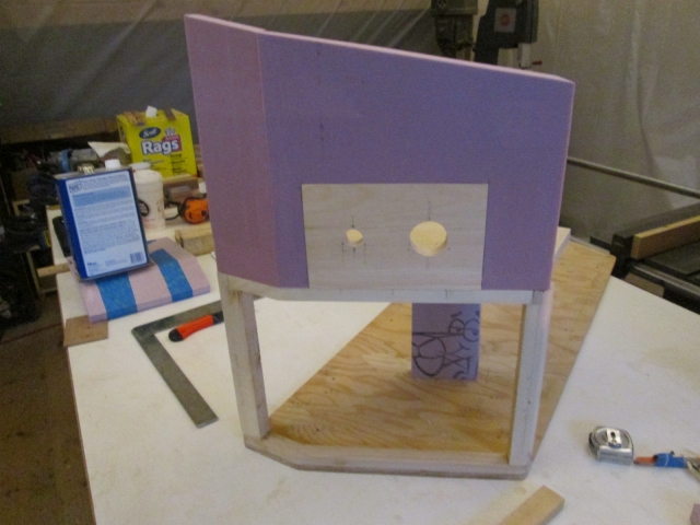
Here is the result.

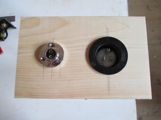
I biscuit joined the lower edge of this “power bulkhead” on to the top edge of the ledge piece and glued it up (which you can see in the pics further down).
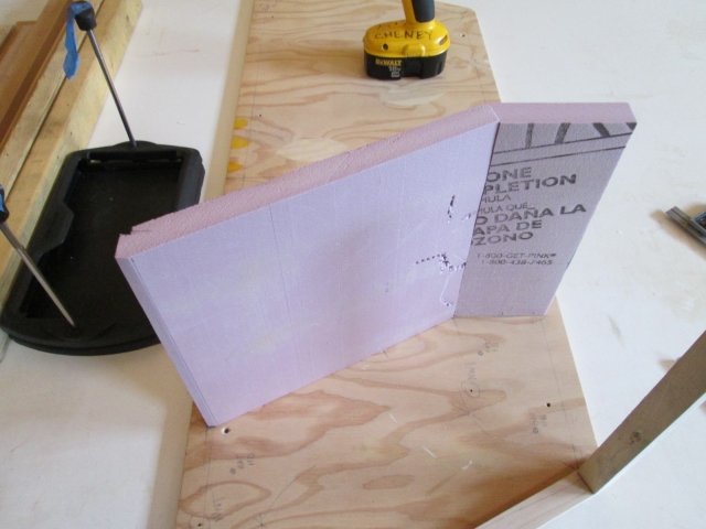
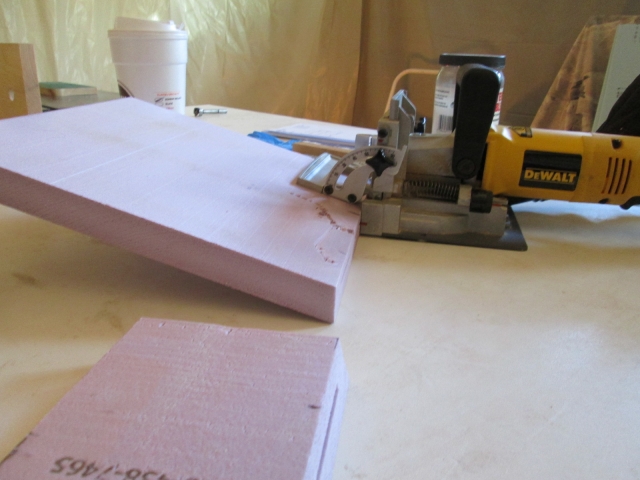
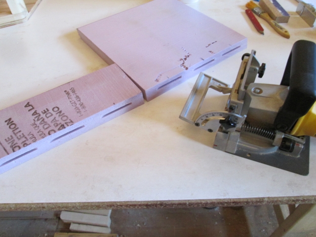
Next up was making the divider bulkhead between the battery compartment and the main section of the tongue box; another mitered joint shown here in the dry fitting stage. This will also support the inner edge of the ledge (the “electronics mezzanine”).
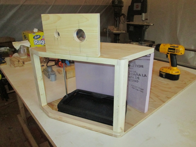
Here you can start to see it coming together, dry fitting the ledge and inner bulkhead.

Rather than trying to make an angled dado in the rear panel of the TB, I made a couple of detail cuts to square off the back edge of the inner bulkhead. This included a little matching nip in the corner of the ledge.
I was pretty sure that I brought bamboo skewers to the shop, but couldn’t find them despite some rudimentary searching, so what the heck, why not use the biscuit joiner to align the edges of the inner bulkhead?
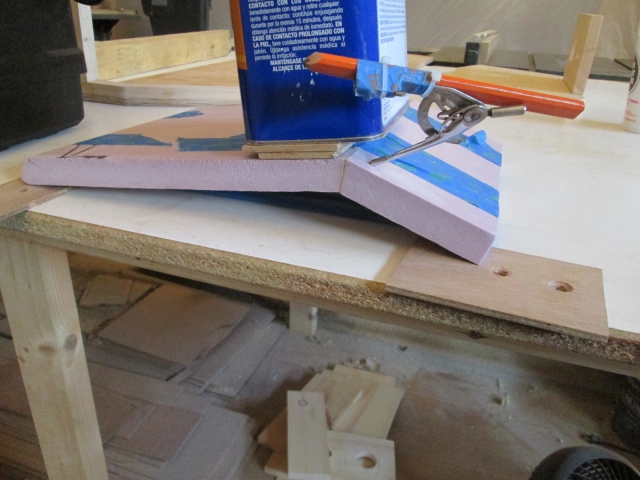
I used blue tape to clamp it. The tape on the inside had more pull than the outside so I used a gallon can of spirits to weigh it down and press the outside edges back together. The spike form the compass made a good pin to hold that outer edge in alignment.
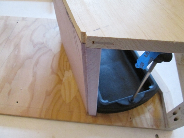
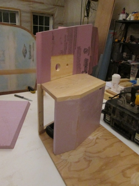
Next I worked on trimming the side panels of the TB down to fit around the new stuff. Although the Kregg screws are dry fit to hold the ledge in place, it isn’t glued yet, and the pink panther looking out from under is just a temporary spacer to support the inner edge while the other piece was curing.
The inner bulkhead had time to set up so I doubled checked that.
Since the power bulkhead is only 3/4 inch thk and the foam is 1 inch thk I beveled the edges of the foam around the bulkhead so that the skin will have an easier time conforming.
In the meantime I had been trimming the front panel of the TB to fit around the front door jamb of the battery compartment, and routing the dadoes for the ledge and inner bulkhead. Haven’t made a panel sled for the table saw yet and had a little false cut on one corner, then made a stupid mistake with the router resulting in another false cut. No problem; we have lots of bits and pieces of foam; I’ll just glue a piece back in there and cut it again. Here the panel is laying flat on the bench, the router guide (strip of wood) is clamped next to the chunk being glued in, and the router is sitting upside down on another piece of foam as a gravity clamp.
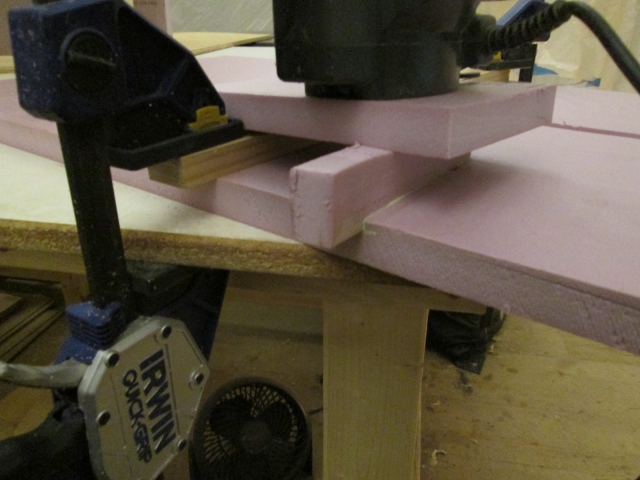
I really wanted to get a pic of the front panel in place, but when things start to go wrong in sets, it’s time to quit for the day. Still, the train kept a rollin’.
It scuffed the back of the flange up a little, but the gasket that is part of the rubber cap lanyard will handle this easily.
Rather than doing a setup on the mill, I decided to just cut the hole with the little jig saw. Laid the pattern out, drilled a pilot hole, threaded the blade and cut it out.
You can also see that I had already drilled the smaller hole for the Perko connector for the solar panel connection.
Unfortunately, the larger hole came out bigger than I wanted resulting in a sloppy fit and less margin for the screws. So I made the piece over again. This time the hole was a little too small. It was a little more off than what I could sand out easily, but not enough to make another cut on the saw; so I used the same technique to make a 5mm thk router template, just a little bigger, and opened up the thicker material using the flush cutting bit.
Here is the result.
I biscuit joined the lower edge of this “power bulkhead” on to the top edge of the ledge piece and glued it up (which you can see in the pics further down).
Next up was making the divider bulkhead between the battery compartment and the main section of the tongue box; another mitered joint shown here in the dry fitting stage. This will also support the inner edge of the ledge (the “electronics mezzanine”).
Here you can start to see it coming together, dry fitting the ledge and inner bulkhead.
Rather than trying to make an angled dado in the rear panel of the TB, I made a couple of detail cuts to square off the back edge of the inner bulkhead. This included a little matching nip in the corner of the ledge.
I was pretty sure that I brought bamboo skewers to the shop, but couldn’t find them despite some rudimentary searching, so what the heck, why not use the biscuit joiner to align the edges of the inner bulkhead?
I used blue tape to clamp it. The tape on the inside had more pull than the outside so I used a gallon can of spirits to weigh it down and press the outside edges back together. The spike form the compass made a good pin to hold that outer edge in alignment.
Next I worked on trimming the side panels of the TB down to fit around the new stuff. Although the Kregg screws are dry fit to hold the ledge in place, it isn’t glued yet, and the pink panther looking out from under is just a temporary spacer to support the inner edge while the other piece was curing.
The inner bulkhead had time to set up so I doubled checked that.
Since the power bulkhead is only 3/4 inch thk and the foam is 1 inch thk I beveled the edges of the foam around the bulkhead so that the skin will have an easier time conforming.
In the meantime I had been trimming the front panel of the TB to fit around the front door jamb of the battery compartment, and routing the dadoes for the ledge and inner bulkhead. Haven’t made a panel sled for the table saw yet and had a little false cut on one corner, then made a stupid mistake with the router resulting in another false cut. No problem; we have lots of bits and pieces of foam; I’ll just glue a piece back in there and cut it again. Here the panel is laying flat on the bench, the router guide (strip of wood) is clamped next to the chunk being glued in, and the router is sitting upside down on another piece of foam as a gravity clamp.
I really wanted to get a pic of the front panel in place, but when things start to go wrong in sets, it’s time to quit for the day. Still, the train kept a rollin’.
Last edited by KCStudly on Mon Jan 05, 2015 2:23 pm, edited 1 time in total.
KC
My Build: The Poet Creek Express Hybrid Foamie
Poet Creek Or Bust
Engineering the TLAR way - "That Looks About Right"
TnTTT ORIGINAL 200A LANTERN CLUB = "The 200A Gang"
Green Lantern Corpsmen
My Build: The Poet Creek Express Hybrid Foamie
Poet Creek Or Bust
Engineering the TLAR way - "That Looks About Right"
TnTTT ORIGINAL 200A LANTERN CLUB = "The 200A Gang"
Green Lantern Corpsmen
-
KCStudly - Donating Member
- Posts: 9640
- Images: 8169
- Joined: Mon Feb 06, 2012 10:18 pm
- Location: Southeastern CT, USA
 Looking GOOD !!!