Professors 7x14 Toy Hauler

Converting Cargo Trailers into TTTs

Re: Professors 7x14 Toy Hauler

Postby professorkx » Wed Jan 14, 2015 12:19 pm

hankaye wrote:professorkx, Howdy;

Interesting with the cabinets. Looking at the framework this morning, yes had a
cup of coffee already, I have a question perhaps more than one. I understand
about the extension on the right (front), to reach the forward wall, but, then
the supports that mount it to the sidewall appear to be on the inside of the face
an again, appear to be at differing widths inside the openings. How is this going to
affect the interior? Also, it appears that you have it designed for 2 doors that raise
up instead of swinging Right and Left???
Am I way off-base or am I close? Thanks for any and all enlightenment.

Constantly curious,

hank


Hank.

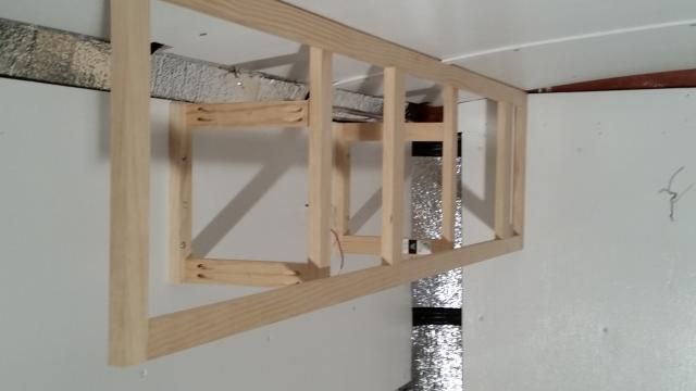
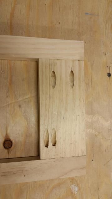
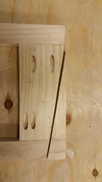
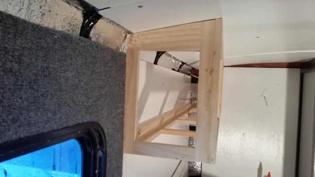
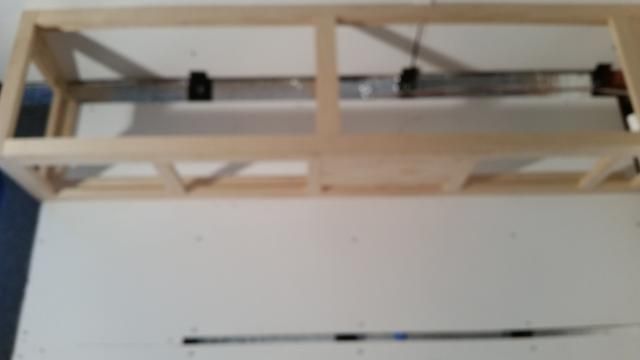
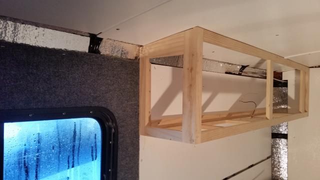
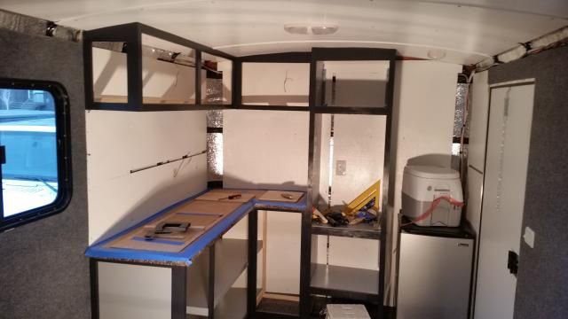
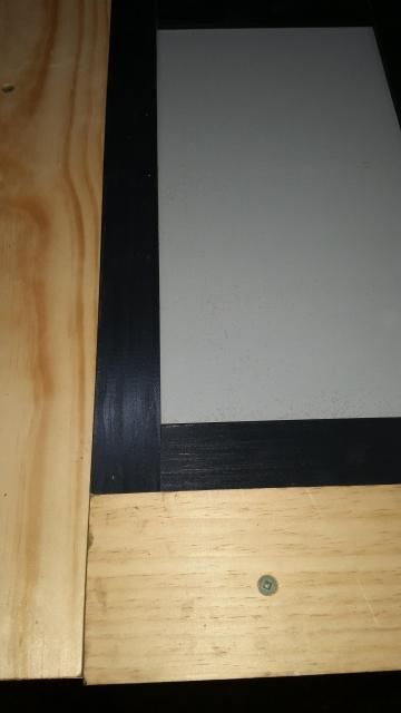
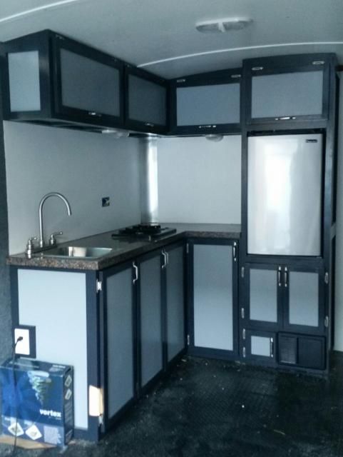
The supports were built to hold the face frame temporarily in place while I build the bottom and end frame in place. You can't see in the photo, but the supports are 3/4 inch above the bottom of the front face frame, which will allow me to complete the bottom frame and glue/staple to the back of the face frame before removing the finished cabinet frame. The top of the face frame will be held in place by a stringer against the ceiling that will attach to the roof supports, and on the bottom with a stringer that will attach to the side wall. The ceiling stringer will have to be beveled so it fits snug against the back of the face frame for good adhesion strength because of the contour of the ceiling, and I will figure out the angle of the bevel before removing the finished frame. Once the bottom and end frames are in place (remember, the end frame has to be cut to the contour of the ceiling, so MUST be built in place), I will remove the entire cabinet frame by removing the four screws holding the supports to the side wall and the four screws holding my new ceiling stringer to the roof supports. With everything back in the shop, I will remove the supports from the cabinet frame and toss them.

I should also note that because of the design of the supports, I can't install the stringer on the side wall until final installation. So, before I remove the finished frame from the wall, I will attach several blocks with screws below the bottom frame against the side wall as a final installation guide. During final installation, the small blocks will hold the cabinet in the right spot on the side wall so I can install the side wall stringer and staple/glue the bottom frame to the side wall stringer.

The supports are also attached to the back of the face frame 7/8 inch below the ceiling. This will allow me to install my ceiling stringer and glue/staple it to the top/back of the face frame before I remove the finished frame from the wall the first time. As you might expect, the supports took some time to design to allow me to build as much as possible on the finished cabinet frame with the temporary supports in place. As I have noted, thinking about the layout on a project like this is an important part of the process or you end up making things a second or third time. I've been a fabricator all my life, so I am used to this kind of thinking. My most difficult projects to date was building these from scratch:
Image
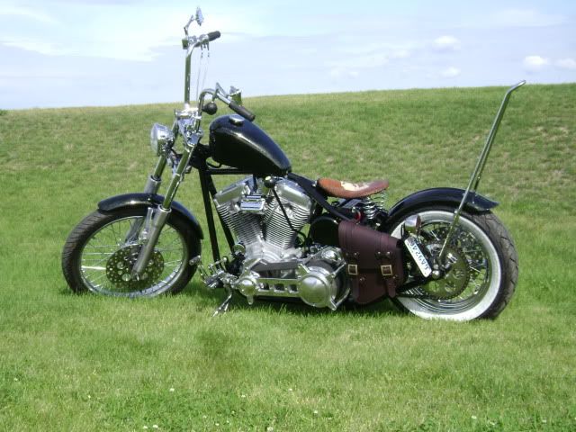
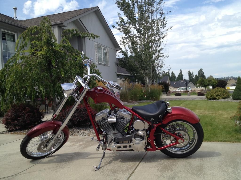
My 8" stretch chopper.

Image
My son's Bobber I built for him for getting home from Iraq alive. He wanted a jockey shifter with a foot clutch, so of course, I fabricated this, and you can see the 8 ball shifter beside the gas tank. The left side foot lever is the clutch peddle, so no clutch lever on the handlebar.

On the doors, I have not decided on flip up or right/left opening, as my wife is very petite at 5' at just over 100 pounds, and fold up doors might not be possible for her to open...even with a stool. So, I will be building a frame to test, but my guts tell me side-by-side doors will be the right ticket.

This top cabinet building plan is somewhat unique, so I will try to remember to take extra pictures. I'm trying to be cautious about posting too many pictures, as I want the pictures that are posted to be helpful, not just take up screen real estate.
User avatar
professorkx
Teardrop Master
 
Posts: 140
Joined: Wed Nov 12, 2014 4:54 pm

Re: Professors 7x14 Toy Hauler

Postby hankaye » Wed Jan 14, 2015 1:24 pm

professorkx, Howdy;

Thanks for taking the time to go as in depth as you did. Very helpful,
I'll be lookin' forward to the pix as you do the actual building of the
cabinet.
As for the items in the pix. I always wanted to have my butt cheeks lit-up
while crusin' ... nice touch!
Truly love the 'Bobber', that's my era... although the 'Billy Bike' from EasyRider
is my all time favorite. Also, please thank your son for his service and I'm glad he
made it home safe and sound.

hank
Striving for a less complicated life since 1949 ...
Every day I beat my own previous record for number of consecutive days I've stayed alive.
hankaye
2000 Club
2000 Club
 
Posts: 2567
Images: 1
Joined: Thu Dec 06, 2012 5:35 pm
Location: S.W. New Mexico

Re: Professors 7x14 Toy Hauler

Postby professorkx » Wed Jan 14, 2015 2:46 pm

hankaye wrote:As for the items in the pix. I always wanted to have my butt cheeks lit-up
while crusin' ... nice touch!


Didn't much care for that rear light setup on the chopper, so it's since been changed to the rear fender behind a vintage 1940's Harley fender rack. The coffin style gas tank only holds 1.6 gallons, and since I ported the gas out each side of the tank in the rear, I don't have reserve, so I'm looking for gas every 70 miles. After running out of gas a number of times, I added bags so I could carry a 1 gallon gas tank designed for bags. Sold the Heritage and the Ultra for lack of use, so have a quick disconnect seat for my wife for local riding. We spend most of our time on a Truimph dual sport, and rode 12,000 dual sport miles in 2014 (about 5000 miles on dirt), but there's just something about riding the chopper that makes the world seem like a better place. No radio, not intercom, just the roar of the Harley EVO out straight pipes...truly tranquil...
User avatar
professorkx
Teardrop Master
 
Posts: 140
Joined: Wed Nov 12, 2014 4:54 pm
Top

Re: Professors 7x14 Toy Hauler

Postby hankaye » Wed Jan 14, 2015 6:30 pm

professorkx, Howdy;

professorkx wrote:
hankaye wrote:As for the items in the pix. I always wanted to have my butt cheeks lit-up
while crusin' ... nice touch!


Didn't much care for that rear light setup on the chopper, so it's since been changed to the rear fender behind a vintage 1940's Harley fender rack. The coffin style gas tank only holds 1.6 gallons, and since I ported the gas out each side of the tank in the rear, I don't have reserve, so I'm looking for gas every 70 miles. After running out of gas a number of times, I added bags so I could carry a 1 gallon gas tank designed for bags. Sold the Heritage and the Ultra for lack of use, so have a quick disconnect seat for my wife for local riding. We spend most of our time on a Truimph dual sport, and rode 12,000 dual sport miles in 2014 (about 5000 miles on dirt), but there's just something about riding the chopper that makes the world seem like a better place. No radio, not intercom, just the roar of the Harley EVO out straight pipes...truly tranquil...


In 1970 I bought a 1969 Triumph Bonneville in England (it was a T-120 not a T-120R), rode it from England to France
then into Spain (ran with the bulls that July), Then back across France thru Belgium and Holland to Denmark ferry
to Sweden, up to Norway then back down to the ferry boat and rode Germany and decided to take a side trip to
through East Germany with the checkpoints to West Berlin, back out and across then to Lichtenstein, Switzerland,
across the top of Italy into Yugoslavia, into Greece then Turkey, across the bridge to Asia and to Erzurum. Then back
to Naples, Italy where I was stationed. All in about 42 days, man were my butt tired, about 4,000 miles I did take a 2.5
day break at an ouzo distillery in Greece, couldn't make it past the free shots at the end of the tour. Kept waking-up
next to my bike...
The T-120 gave me an extra gal. in the gas tank and a compression release lever on the right handlebar.
My last bike was a '77 FXE, mostly stock. Sorry no pix, irate ex #2 & 4 trashed all the photos.

hank
Sorry about the hi-jack...
Striving for a less complicated life since 1949 ...
Every day I beat my own previous record for number of consecutive days I've stayed alive.
hankaye
2000 Club
2000 Club
 
Posts: 2567
Images: 1
Joined: Thu Dec 06, 2012 5:35 pm
Location: S.W. New Mexico
Top

Re: Professors 7x14 Toy Hauler

Postby professorkx » Tue Jan 20, 2015 1:28 pm

Not much progress for a three day weekend, but I helped my son convert his Jeep to power brakes and hydraulic clutch to go along with the V8 Chevy motor swap, and had to custom build the brake lines to the proportioning valve, but it was a fun project as well.

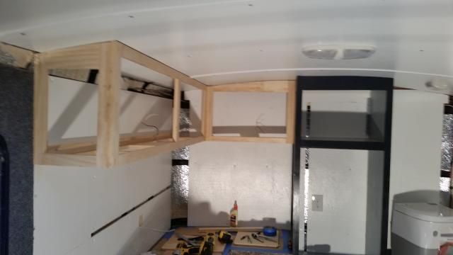
On the trailer, the focus was to finish the upper cabinets, and of course, everything had to be shaped to either the ceiling contour or the front wall contour, so took extra time. I also had to build these in place to adjust for any out of square issues with the trailer. First up was the end piece for the upper face frame that is already in place.

Image
My starting point for the weekend.

Image
Since I knew I was going to have to cut the top to fit the ceiling, I started with a rectangular frame with a larger style on the top of the frame. I also offset my pocket holes on the edge that would fit to the wall, as I didn't want to cut into my pockets during trimming.

Image
The amount that was trimmed to fit

Image
End piece in place.

Next up was building the bottom. Yes, yes, you can see the bottom frame in the picture above, but I forgot to take a picture with just the end piece, so had to settle for the one with the bottom frame already built. The bottom frame was pretty straight forward, just a long rectangle with a wider piece at the end for trimming. Instead of putting this in place and marking, I just laid it on top of the counter, spaced off the wal 1/4" to compensate for carpet thickness since one end was on the wall carpet, and marked my contour. You will also notice a 1x6 that is positioned for the light above the sink and stove. Trimmed the end and stapled into place (sorry for fuzzy photo)

Image
You will also notice that I have removed the temporary braces in this photo. I was going to remove the entire cabinet frame for painting, but without a back, and given the length of the cabinet, I decided to leave it in place to ensure I wasn't building a second frame. Just too flimsy to remove.

Image
Final picture of the finished unit.

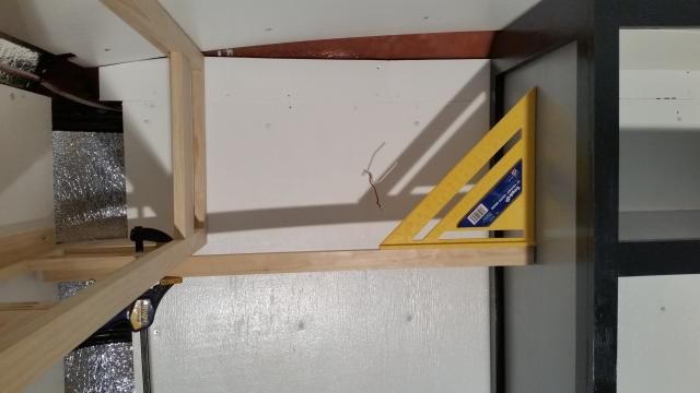
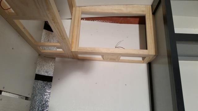
The final cabinet was the connecting cabinet to the tall cabinet that would hold the refrigerator. First, I needed to make sure that the cabinet I had just finished was square to the tall cabinet.

Image
Given that the wall is not square, this was as much luck as skill. As you can see, the bottom of the cabinet is square to the tall cabinet, a great final starting point.

Image
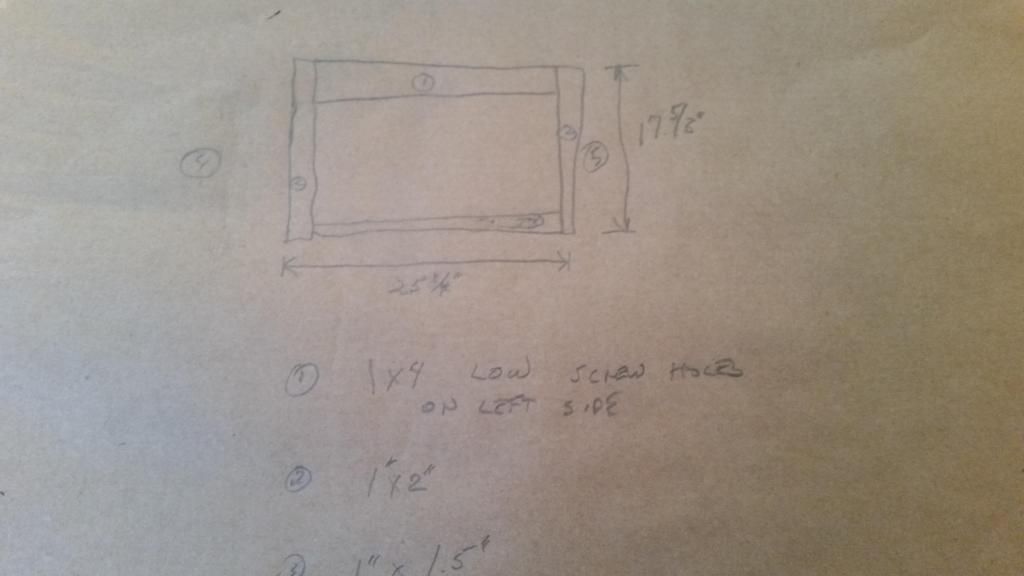
I have not shown many pictures of the design process, but I draw out everything before I build, and I make a lot of notes. This has helped ensure that I have not built any cabinet a second time because of a measurement error. As you can see, I started with a frame with square dimensions, and then cut down the top style to follow the ceiling. In addition, I wanted the bottom of the top style to be in the same position as the cabinet to which it would attach, so I had to custom cut the top piece to 3 3/16 inch wide.

Image
I used clamps to hold the frame in place, marked the contour with my marking gauge, cut and installed. Perfect fit the first time.

The bottom was built in place, one style at a time, as it was small, so I wasn't trimming a thick rear style. Instead, I used a 1x2 and cut a 6 degree angle on each end. This also required that I relieve both ends with a slight angle so my 1/4 inch back splash would butt against the bottom style without any gaps. The front style was easy, as it has 90 degree ends.

Image
Difficult to get a good picture, but here you go. The 1x6 in the middle is for one additional light over the coffee pot.

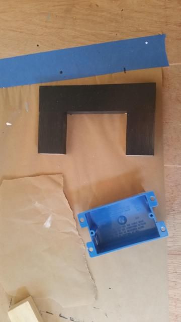
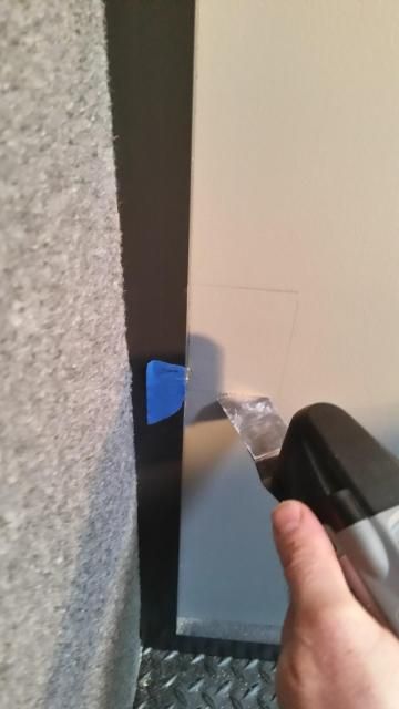
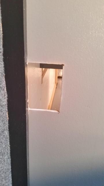
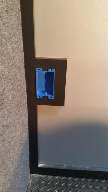
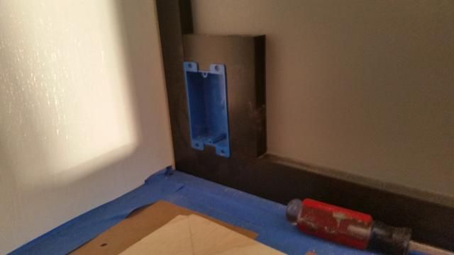
Speaking of coffee pots, I need a plug at the end of the counter, as well as at the end of the bottom cabinet for a space heater. I had planned for this, but didn't want to build from the start, so just built a small frame for the electrical box and installed at the end of the process.

Image

Finished frame and electrical box all painted and ready to install. I held in place, marked the interior and cut with my vibrating saw.

Image

Image

Image
I just held it in place and stapled from the rear to the panel. This one is for the space heater.

Image
Plug for the coffee pot. This one will actually go to a switch so I can select inverted power or shore power. The refrigerator plug will be the same, with a switch for inverted or shore power.

Image
Final progress for the weekend.

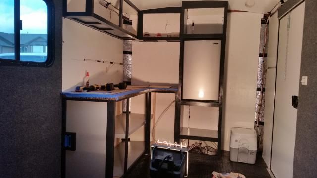
Last picture with the refrigerator in place. I had a whole 1/4 inch to spare on the hinge side.

Image

With the refrigerator in place, I can build the door locking system as well replace the front legs with a bar that will be screwed to the floor from the cabinet below to keep the refrigerator in place.
User avatar
professorkx
Teardrop Master
 
Posts: 140
Joined: Wed Nov 12, 2014 4:54 pm
Top

Re: Professors 7x14 Toy Hauler

Postby lrrowe » Tue Jan 20, 2015 3:15 pm

Professorkx,

Boy you sure are making progress. Looking very good!
Bob

First Post on Purchase of Trailer: http://www.tnttt.com/viewtopic.php?f=42&t=60722
Hot water infloor and radiator heating project:[url]http://www.tnttt.com/posting.php?mode=reply&f=54&t=62327[/

Image Image
User avatar
lrrowe
Donating Member
 
Posts: 3285
Images: 439
Joined: Sun Feb 10, 2013 5:54 am
Location: SW Virigina
Top

Re: Professors 7x14 Toy Hauler

Postby 2Tornadoes » Tue Jan 20, 2015 5:51 pm

Just have to say that your build is very inspiring! It looks like you're using 1x for the framework of your cabinets. I've seen this in a lot of other builds and I wonder how that holds up to all the road shaking? We like to camp in a lot of wilderness areas and sometimes have to deal with washboard dirt roads. I'm trying to plan our build so we don't open the door upon arrival to a big mess inside.

Maybe I'm over-thinking this and we'll be fine?
2Tornadoes
Teardrop Builder
 
Posts: 34
Joined: Tue Jan 13, 2015 4:25 pm
Location: Colorado
Top

Re: Professors 7x14 Toy Hauler

Postby hankaye » Tue Jan 20, 2015 9:36 pm

professorkx, Howdy;

Dang! Your experience is showing, all over the place ...
Good looking job.

hank
Striving for a less complicated life since 1949 ...
Every day I beat my own previous record for number of consecutive days I've stayed alive.
hankaye
2000 Club
2000 Club
 
Posts: 2567
Images: 1
Joined: Thu Dec 06, 2012 5:35 pm
Location: S.W. New Mexico
Top

Re: Professors 7x14 Toy Hauler

Postby abqlloyd » Tue Jan 20, 2015 10:01 pm

Looking great. Can you expand on your shore/inverter switch? I went with a transfer switch specific to my Prosine inverter. I'm curious how you plan to switch between.
abqlloyd
Teardrop Master
 
Posts: 273
Images: 3
Joined: Mon Aug 08, 2005 11:47 pm
Top

Re: Professors 7x14 Toy Hauler

Postby professorkx » Wed Jan 21, 2015 12:50 pm

abqlloyd wrote:Looking great. Can you expand on your shore/inverter switch? I went with a transfer switch specific to my Prosine inverter. I'm curious how you plan to switch between.


I'm not doing anything great and wondrous, as I just need to switch the hot and neutral in tandem to either shore power or inverted power. I also want to be able to switch each item individually so I don't overload my 1500 watt Cobra unit. So, just going to fabricate a simple switch panel that I can hide behind a door that will hold three dual pole/dual throw rocker switches, essentially, the best looking switch I can find at a reasonable price that will handle up to 15 amps on AC.
User avatar
professorkx
Teardrop Master
 
Posts: 140
Joined: Wed Nov 12, 2014 4:54 pm
Top

Re: Professors 7x14 Toy Hauler

Postby professorkx » Sun Jan 25, 2015 9:09 pm

The weekend has arrived, so time to work towards completion so we are ready for spring. I decided I wanted to finish the electrical and test before I covered the wires anymore than they already are, especially in the front corner by the toilet and where the walls meet the ceiling. If I've hit a wire with a screw, I want to be able to get to the wire easily and fix, so it was time to install the power panel.

However, the first thing was to build the wiring harness and switch system for switching three plugs from shore power to the inverter. I am using a Cobra 1500 watt inverter with a remote on/off, so it won/t be able to handle a lot of load. As a result, I needed to be able to switch plugs for the Refrigerator, Coffee plug on the counter and the plug for the ceramic heater independent of one another.

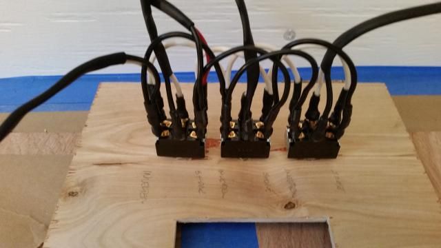
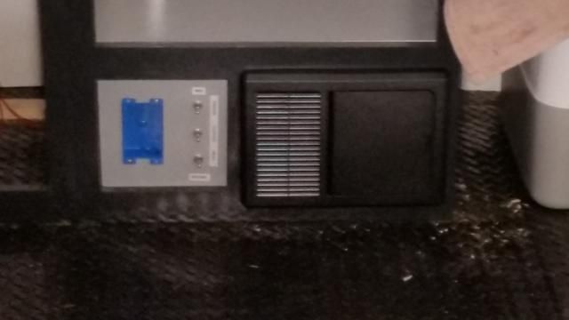
First I installed the switches in a 1/4 inch plywood panel that I would staple in place once complete. The switches are dual throw, dual pole, On/On switches, so no middle off position, and rated for 20 amps at 120 AC volts. My thought was that I needed to switch both neutral and hot from shore power to the inverter, so my switches each had 6 poles. The middle two will go out to the plug, while the top two will go out to shore power and the bottom two to the inverter.

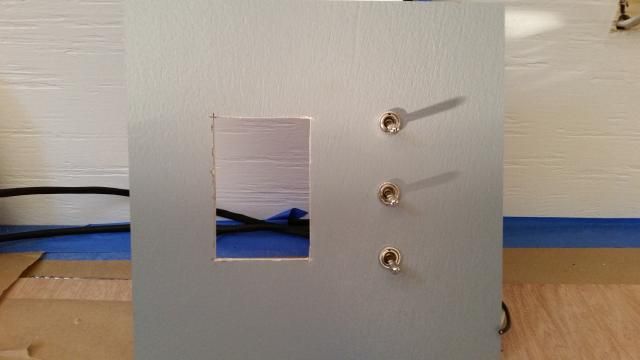
I started by building four jumper wires (two white and two black), soldering each wire to an eye connector. The jumpers were intended to allow me to connect shore power and inverted power to only one switch and have all switches receive the same power. As I installed the jumpers, I used marine heat shrink (marine heat shrink has heat activated glue to seal for water) on each terminal so I didn't have any exposed wires that could short. With all wires installed, I have one pair that will go to the inverter, one pair that will go to the power panel, and three pairs that will go to the three plugs. Took about 3 hours to build the entire setup. Pictures of the front and back of the panel before installation.

Image
Front. The hole is for a box that will hold the inverter remote power switch

Image
Rear of the panel. Everything is color coded, and I changed out the white wire on the inverter pair for a red wire for easy identification. I need to wire a 110 plug on the end of this pair, and take the ground to the common ground for group of wires to the plugs.

Image
Everything in place after a lot of work.

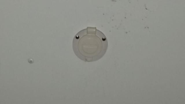
I used an external plug that will take a standard 110 receptical, something others have used on this forum. Here is the plug from the outside.

Image

Doesn't look like much was accomplished, but trust me, this was a lot of work.

I will test next weekend and address any problems. Since we have little crumb crunchers that will be on the floor scooting around during camp trips, I will need to build a door over the plugs so little finger don't find them.
User avatar
professorkx
Teardrop Master
 
Posts: 140
Joined: Wed Nov 12, 2014 4:54 pm
Top

Re: Professors 7x14 Toy Hauler

Postby professorkx » Sat Feb 21, 2015 8:55 pm

It been a while since I posted any progress pictures, but life has gotten in the way of progress, so progress was slow.

Over the last 4 weeks, I found time to make and install all of the cabinet doors. I've made a lot of doors in the past, but wanted to try something different since these doors didn't involve a big investment. If I didn't like the result, I knew I could toss the doors and start over because of the low investment.

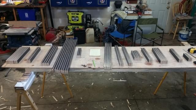
My intent was to rip a grove in the stiles and rails that would comprise each door, then install a panel made of 5mm underlayment. The first step was to cut the groove. This can be done with a router, but I wanted to use the table saw...for no special reason.

Before I could start, I had to measure the size of each opening, add 3/4 inch for overlap (3/8 inch on all sides), and determine the number of stiles and rails that would be required in each size. With this done, I painted everything with one coat of paint to make final painting easier. I started my groove by running each stile and rail through the table saw, which gave me a groove the width of the blade in each board.

Image

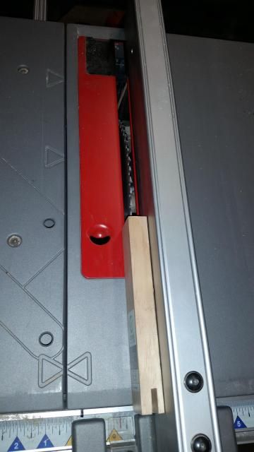
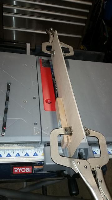
This first groove is too narrow for the panel, so I needed to make another pass and widen the groove. I had already cut a length of scrap luan, and attached it to the fence for the second pass. The luan moved the board away from the fence a little for the second pass, which gave me the perfect width for the panel that I would install during assembly. I could have moved the fence for the second pass, but this would have required some trial and error adjustment, which was eliminated by leaving the fence in the same place and adding the luan spacer.

Image

I cut every board before breaking down the saw, as this made sure every groove was in the exact same spot on each board and the same width.

Image

Next up, assembly. The boards in the picture above are organized by size, with the stile and rails separated by the yellow pad on the table. With this many boards, organization is very important so the correct stile goes with the correct rail.

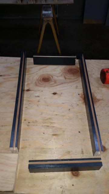
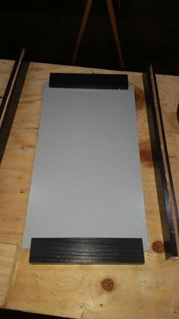
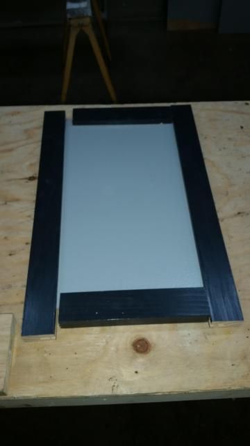
For assembly, I pulled two stiles and two rails and placed them on my table. I measured the size of the panel and cut the panel from 5mm sheets that had already been painted on both sides. I started by sliding the rails on the panel, and then sliding the stiles in place.

Image

Image

Image

The panel helped make the door square, but to make sure once glue was added, I screwed two 1x4 pine pieces to the table in a square corner that I used to ensure every corner was square as I taped the stiles and rails tight in place.

Image

These doors took longer to make than just making a frames using pocket screws and stapling a panel on the back, but these doors don't weigh much and they look pretty good. I set the sink, faucet and stove in place to see how everything looks, and here is a picture of the doors installed.

Image

The refrigerator is permanently installed in this picture. I removed the front two adjustable legs, cut a 1x2 to the correct length, drilled holes and used bolts to bolt in place using the front leg screw holes. Once I pushed the refrigerator into place, I screwed into the new front leg from underneath so it was attached to the floor of the opening. The rear leg was made of hat channel, so I was able to screw the rear leg to the floor from underneath using self taping screws.

The only other issue was holding the door closed during transport. My door is reversible, so I had two screws in the top to which I attached a short length of flat stock aluminum that I painted black. I drilled a hole in the front of the flat bar that allows me to use the hinge pivot and a pin that holds the door closed. I drilled a hole in the stainless bolt I used for a pin and inserted black 14 gauge wire so the pin won't get lost. Didn't take a picture, but I can if anyone is interested.

The cabinets are finally finished. Next up is plumbing for water and propane. I think I'm actually going to finish before spring riding/camping season arrives. Phew.
User avatar
professorkx
Teardrop Master
 
Posts: 140
Joined: Wed Nov 12, 2014 4:54 pm
Top

Re: Professors 7x14 Toy Hauler

Postby abqlloyd » Thu Feb 26, 2015 11:48 pm

Outstanding work. Thanks for sharing.
abqlloyd
Teardrop Master
 
Posts: 273
Images: 3
Joined: Mon Aug 08, 2005 11:47 pm
Top

Re: Professors 7x14 Toy Hauler

Postby Jiffypop207 » Fri Feb 27, 2015 8:25 am

Looks Great!
User avatar
Jiffypop207
Teardrop Master
 
Posts: 205
Joined: Wed Sep 09, 2009 8:39 pm
Location: Old Orchard Beach, ME
Top

Re: Professors 7x14 Toy Hauler

Postby Gonefishin » Fri Feb 27, 2015 12:10 pm

That's just full-on skills at work there. Nice job, very professional. :applause:
User avatar
Gonefishin
Donating Member
 
Posts: 528
Images: 119
Joined: Sat Oct 03, 2009 7:38 pm
Location: NE Utah
Top

PreviousNext

Return to Cargo Trailer Conversions

Who is online

Users browsing this forum: No registered users and 1 guest