The Poet Creek Express - Foamie Hybrid

Canvas covered foamies (Thrifty Alternatives...)

Moderator: eaglesdare

Re: The Poet Creek Express - Foamie Hybrid

Postby OP827 » Sat May 23, 2015 11:41 am

I agree, was just curious, I also use mostly mechanical cut power tools, a bit messy but with my saw dust collect big plastic barrel maintenance free shop vac separator :), not that bad at all.
User avatar
OP827
Donating Member
 
Posts: 1595
Images: 414
Joined: Fri Apr 25, 2014 7:27 pm
Location: Bruce County Ontario

Re: The Poet Creek Express - Foamie Hybrid

Postby KCStudly » Sat May 23, 2015 7:47 pm

I brought my shop vac from home today and had a bit of a cleanup before getting started; needed doing as I have been reluctant to load up Karl’s new vac. Despite being much louder and not as convenient to use (short stiff hose and no remote start feature) it seemed to move a lot more air and made short work of picking up all of the accumulated debris.

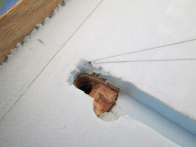
The router had bobbled off of the wireway grommet making an Eeyore (donkey track), so rather than trying to route the grommet fair to the bottom of the wireway I just chiseled out a little and rounded the entry into the hole.
Image

I had already rolled the entry into the galley light block slightly with a drill bit, but the approach angle had changed slightly and I wanted to take it down even with the bottom of the wireway (1/2 wide x 1/2 deep) so I chiseled that out a bit, too. Made sure not to get into the tip of the light mounting screw coming up from the other side (down in the smaller hole).
Image

A little out of sequence, I shaved a couple of small pieces of foam and shoved them into the small gaps around the light block; mostly just to prevent dead ends and unwanted catch points should I ever need to fish wires blindly.
Image

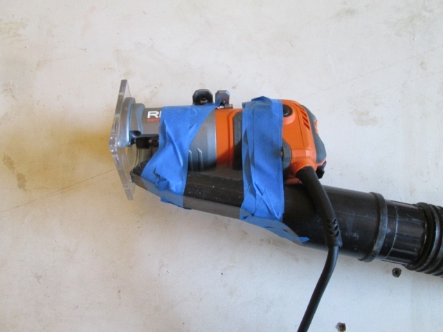
Getting ready to router the horizontal wireway for the hatch clearance lights, I adapted the shop vac nozzle with blue tape. This would prove to be awkward because the hose was kind of short and would have to be held up very high.
Image

I made a short stick to prop the hatch open just enough to get some spring clamps under the edges, but not so high that I couldn't reach while standing on the step stool. The Red Grandis stick used as a guide fence is the same one I have been using as a temporary hatch prop.
Image

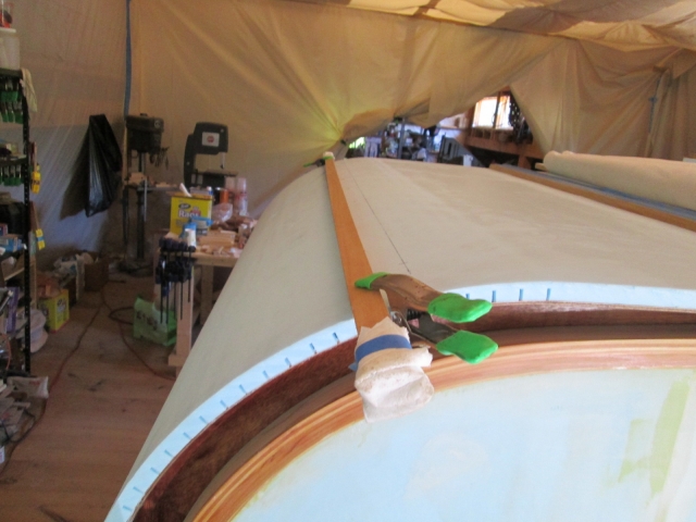
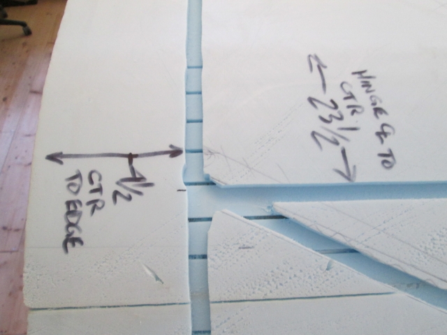
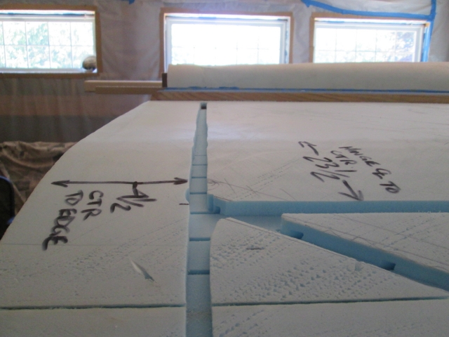
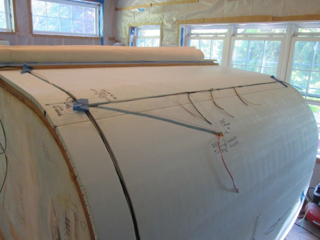
Photo documentation locating the wire ways so that I can find them again after the top layer of foam goes on. This is the main junction that will be located under the upper left clearance light blister.
Image
Image

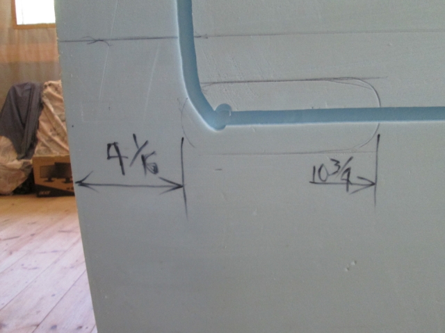
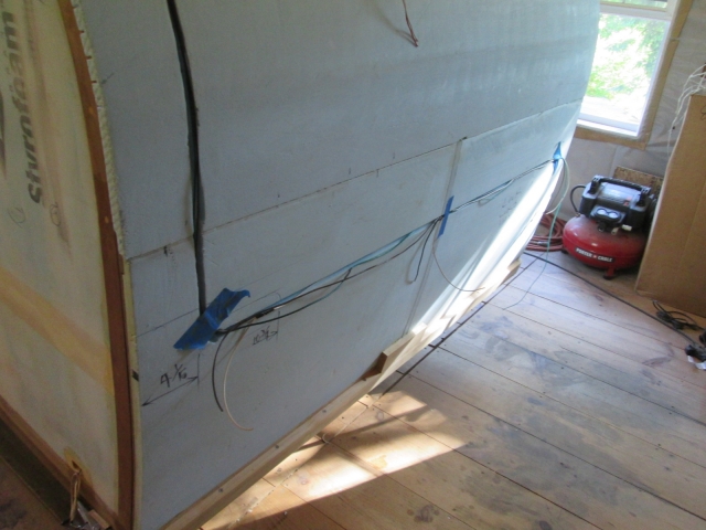
Left taillight. The oval area will be routed out some more to allow space for the pigtail plug and back of the light housing. Still thinking about the sequence on that one.
Image

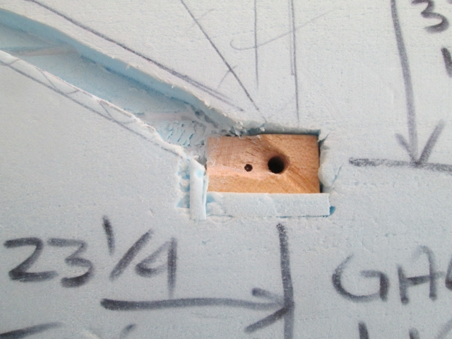
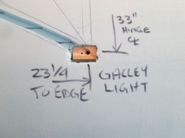
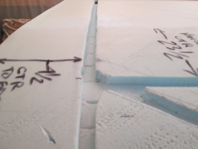
Galley light block location dim’s.
Image

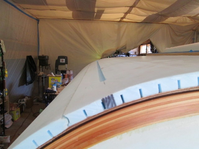
Black sharpie marks on edge of hatch foam in line with horizontal wire ways will also help locate after top layer of foam goes on.
Image

Used the PL300 to seal all of the exposed kerfs in the wire ways.
Image
Image

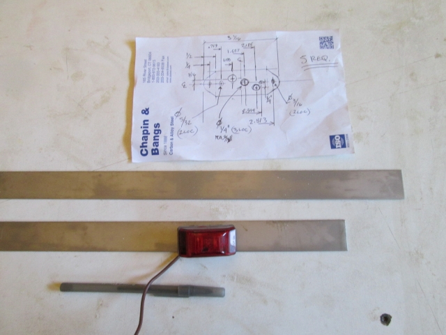
Chris and Karl had relatives visiting; gave tour of build to his brother in law. I heard Karl demonstrating the shear and break press, and shortly thereafter he brought me these 18 gauge x 1-1/8 wide strips of stainless steel that I had requested for the clearance light mounting plates. Now that the weather is good I’ll get back to those when they are needed. I’ll drill all of the holes on the mill before cutting the individual plates out.
Image

Speaking of the weather, it was a beautiful blue sky day today with lovely cool temps.

No better time than the present to prefab the wire harness for the hatch. I laid the ground (white) and running light (brown) wires in to the troughs with a little blue tape to hold them in place and marked where all of the T-splices needed to be. My fancy wire gripper strippers worked well to cut and spread the insulation midway on the main runs so that I could add pigtails for each fixture. I figured this would be an easier way to fish the pigtails out where I can join them with the fixtures, rather than having to find slack in the main runs later. Soldered, cleaned away flux and shrink wrapped all connections.
Image
Image

Where the upper and lower runs crossed I bared both wires and twisted them together in a four way connection (rather than cutting the wires), resulting in the pigtails for the clearance light there (in my hand). This is that main junction under the upper left clearance light, and probably the point that I will pull all of these wires from, pulling out to the ends of the three different branches (right taillight, right clearance light and main grommet).
Image

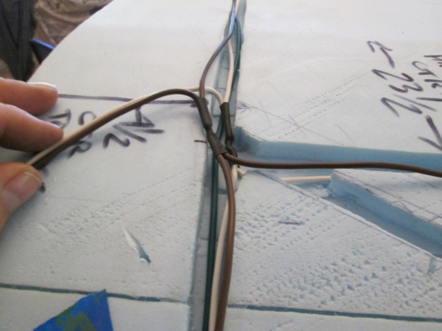
The green (right turn/stop) is just a straight run to that fixture and is laid in below these. The yellow (left turn/stop) and pair for the galley light (red/hot and white/ground) are yet to come. I’ll set those up tomorrow, do some filling of gaps here and there, and hopefully get into the second layer of foam.

I spotted Karl's old dead shop vac under the stairs and figure that would be a good starting point for a cyclone separator; already has the right sized connections, plenty of volume and already mounted on wheels, but is another project for another day.
Last edited by KCStudly on Mon Aug 03, 2020 8:06 am, edited 2 times in total.
KC
My Build: The Poet Creek Express Hybrid Foamie

Poet Creek Or Bust
Engineering the TLAR way - "That Looks About Right"
TnTTT ORIGINAL 200A LANTERN CLUB = "The 200A Gang"
Green Lantern Corpsmen
User avatar
KCStudly
Donating Member
 
Posts: 9640
Images: 8169
Joined: Mon Feb 06, 2012 10:18 pm
Location: Southeastern CT, USA

Re: The Poet Creek Express - Foamie Hybrid

Postby daveesl77 » Sat May 23, 2015 7:56 pm

Beautiful work, as always! The idea of using the photo documentation for future is brilliant

dave
*******
Dave and Regina - Enjoying old age, a LOT!

Build Journal - http://www.tnttt.com/viewtopic.php?f=50&t=62386
User avatar
daveesl77
Donating Member
 
Posts: 871
Images: 273
Joined: Tue Jan 27, 2015 4:33 pm
Location: Pocahontas County, West Virginia
Top

Re: The Poet Creek Express - Foamie Hybrid

Postby KCStudly » Sat May 23, 2015 8:15 pm

.
It is a very good idea that I can not take credit for. I think the first place I saw the technique used was on Tom's Silver Beatle build, IIRC.

Thanks for watching and for the kind comments. :D
KC
My Build: The Poet Creek Express Hybrid Foamie

Poet Creek Or Bust
Engineering the TLAR way - "That Looks About Right"
TnTTT ORIGINAL 200A LANTERN CLUB = "The 200A Gang"
Green Lantern Corpsmen
User avatar
KCStudly
Donating Member
 
Posts: 9640
Images: 8169
Joined: Mon Feb 06, 2012 10:18 pm
Location: Southeastern CT, USA
Top

Re: The Poet Creek Express - Foamie Hybrid

Postby Wobbly Wheels » Sat May 23, 2015 10:14 pm

Thx for the Mog porn pics :thumbsup:
The M35s are what they are and all, but the Euros definitely got it right with those trucks.

Where the upper and lower runs crossed I bared both wires and twisted them together in a four way connection...

Soldered or crimped as well ?
I wouldn't presume to preach to you and I don't recall if you decided on tinned wire or not, but if not you might be setting yourself up for the 'creeping black death' as corrosion inevitably sets in if the wires are just twisted together.

...so rather than trying to route the grommet fair to the bottom of the wireway...

So you've got a grommet going into the hole for chafe protection ?
Maybe I'm not on the same page but, with your mention of "prevent dead ends and unwanted catch points should I ever need to fish wires blindly", why not oversize the holes enough to run tubing in them as a raceway ?
That said, I can see how any tubing you run might kink in the hard 90, making fishing much more difficult.

Not picking in any way whatsoever, just curious and trying to get on the same page.
User avatar
Wobbly Wheels
Donating Member
 
Posts: 1080
Joined: Tue Mar 15, 2011 9:51 am
Top

Re: The Poet Creek Express - Foamie Hybrid

Postby KCStudly » Sat May 23, 2015 11:56 pm

I am always open to learning things that I don't know. I have seen black wires in very old wiring and it is tough to deal with, but I assumed that it was just from age and the gradual incursion of moisture.

These wires do happen to be tinned, but not all of my wiring is. I decided that the extra expense wasn’t warranted and that the cost of all of the wiring components would already be a big enough chunk beyond the original budget. I can see where there would be no compromise in the salt water applications that you deal with, but that shouldn’t be a factor here. Not the best, but it is a calculated decision.

Not crimped and no connectors, at least not here. To make these pigtail additions I used the gripper stripper pliers that cut the insulation and forced it back about 3/8 to 1/2 inch leaving a bare spot mid span on the wire. Then I stripped about the same amount of insulation, perhaps a little more off of the end of the pigtail. Laid the stripped end of the pigtail wire parallel to the main wire with the ends of the insulation matched up and twisted the loose end of the pigtail around the bare part of the main wire. Then soldered. Then cleaned. Then shrunk. For the 4 way connections I did the same; split the insulation open about 3/8 to 1/2 inch, laid the wires parallel, twisted them around each other and soldered. I’ll take some more detailed pics of the process tomorrow.

I know some people don't like soldering because they claim vibration can cause a break at the solder where it is no longer flexible, but I have seen more problems with bad crimps and cheesy knife style clip-on splices.

Not a rubber grommet in the traditional sense, just what I have been calling the wooden washer like thing that I glued on to the back of the hole in the hatch skin where the wires will enter the hatch. I'm not that worried about chaffing here, just being particular with the small details and trying to ease the edges so the wires don't kink at the turn so much.

Re: pulling or fishing the wires. I really haven't decided how I am going to do this yet. The idea of using some sort of tubing as a wireway sounds great until you start to look at the route, and how much extra space the tubing itself would take up. To get the same 6 wires thru a conduit the cuts in the foam would need to be much larger to fit the tubing and that doesn't address what happens at the junctions where some wires go one way and others go the other way.

I surely would like to be able to fish new wires if the need should arise, so I am keeping that in the back of my mind. The galley light would be the hardest to do because there is no room in the fixture’s end cap for any kind of connector, any extra wire for a splice connection, or even the added stiffness of a shrink wrapped solder joint. I have enlarged the hole in the housing base as much as I dare to without accidentally cutting or breaking off the plastic bosses for the end cap, but even that may not be enough to fish the shrink wrapped wires through. On top of all of this, the hole in the blocking can only be so large because it is right next to the mounting screw for the fixture.

I could build the wires in as I put the next layer of foam on, but I have my doubts about being able to place the needed access holes in the top layer accurately prior to attaching. The flip side is cutting the holes after the foam is down, but then there is the risk of cutting the wires.

So right now the plan is to take it to the next step and start dry fitting the next layer of foam. If I feel that I can be accurate enough to precut some access holes and get them to lay down in the right locations (not much confidence from my prior experiences), then I might lay the wires in first. More likely I will lay in some pull strings and use them to pull the wires in after the fact, or I think I could even get the pull strings thru after the fact… except maybe for the galley light. Even that I could probably vacuum a string thru close enough to pluck it thru with a small hook on the end of some fine MIG wire.

By intent these runs are more or less straight from fixture to fixture and the point to point distances are relatively short, so it shouldn’t be that much trouble. I made the pigtail splices so that they all lay down in the direction that the wires would be pulled; and so that the splices would each pass by their intended hole location enough to be able to hook the pigtail and turn it out of its intended port.
KC
My Build: The Poet Creek Express Hybrid Foamie

Poet Creek Or Bust
Engineering the TLAR way - "That Looks About Right"
TnTTT ORIGINAL 200A LANTERN CLUB = "The 200A Gang"
Green Lantern Corpsmen
User avatar
KCStudly
Donating Member
 
Posts: 9640
Images: 8169
Joined: Mon Feb 06, 2012 10:18 pm
Location: Southeastern CT, USA
Top

Re: The Poet Creek Express - Foamie Hybrid

Postby Wobbly Wheels » Sun May 24, 2015 2:37 am

I decided that the extra expense wasn’t warranted

Yep, completely get that: we all build to what suits us best.

More likely I will lay in some pull strings and use them to pull the wires in after the fact, or I think I could even get the pull strings thru after the fact…Even that I could probably vacuum a string thru...

Hehe, looks like we are indeed on the same page.

I know some people don't like soldering...

Thread wars have been started over this very topic so I ain't gonna touch it :noyes:

these runs are more or less straight from fixture to fixture and the point to point distances are relatively short

At the end of the day, we're just building trailers...how many details could there possibly be ? :lol:
User avatar
Wobbly Wheels
Donating Member
 
Posts: 1080
Joined: Tue Mar 15, 2011 9:51 am
Top

Re: The Poet Creek Express - Foamie Hybrid

Postby KCStudly » Sun May 24, 2015 10:21 am

Wobbly Wheels wrote:...how many details could there possibly be ?


Well, all of them, of course! :R :lol: :lol: :lol: :D
KC
My Build: The Poet Creek Express Hybrid Foamie

Poet Creek Or Bust
Engineering the TLAR way - "That Looks About Right"
TnTTT ORIGINAL 200A LANTERN CLUB = "The 200A Gang"
Green Lantern Corpsmen
User avatar
KCStudly
Donating Member
 
Posts: 9640
Images: 8169
Joined: Mon Feb 06, 2012 10:18 pm
Location: Southeastern CT, USA
Top

Re: The Poet Creek Express - Foamie Hybrid

Postby GPW » Sun May 24, 2015 1:05 pm

Re: wiring ... we always make a "mechanical connection “ that is then soldered .

Coming along Nicely KC ... Glad the weather is pleasant. :thumbsup: 8)
There’s no place like Foam !
User avatar
GPW
Gold Donating Member
 
Posts: 14920
Images: 546
Joined: Thu Feb 09, 2006 7:58 pm
Location: New Orleans
Top

Re: The Poet Creek Express - Foamie Hybrid

Postby Fred Trout » Sun May 24, 2015 2:47 pm

...how many details could there possibly be ?


"The space shuttle has more than 2.5 million parts..."

Hopefully our teardrops are somewhat simpler :R
User avatar
Fred Trout
The 300 Club
 
Posts: 396
Joined: Fri May 08, 2015 4:30 pm
Location: SW Montana
Top

Re: The Poet Creek Express - Foamie Hybrid

Postby KCStudly » Sun May 24, 2015 3:01 pm

Back when I worked on submarines we had the NASA guys come visit the shipyard. They were humbled by the complexity and number of components that go into a nuke sausage, the shear magnitude of the program and planning that goes into the construction sequence. It wasn't rocket science, but it might as well have been.

I couldn't do either of those jobs by myself, but with the help of this forum, and the ever present support of my friend Karl, I can do this! :thumbsup:
KC
My Build: The Poet Creek Express Hybrid Foamie

Poet Creek Or Bust
Engineering the TLAR way - "That Looks About Right"
TnTTT ORIGINAL 200A LANTERN CLUB = "The 200A Gang"
Green Lantern Corpsmen
User avatar
KCStudly
Donating Member
 
Posts: 9640
Images: 8169
Joined: Mon Feb 06, 2012 10:18 pm
Location: Southeastern CT, USA
Top

Re: The Poet Creek Express - Foamie Hybrid

Postby Fred Trout » Mon May 25, 2015 1:44 am

Hey, the worst that will happen is we will get wet & cold if the teardrop fails and that happened a number of times when using a tent. :cry:

The nice thing about foamies is they can be fixed without serious consequences when we break em since they don't go into space or hundreds of feet underwater.
User avatar
Fred Trout
The 300 Club
 
Posts: 396
Joined: Fri May 08, 2015 4:30 pm
Location: SW Montana
Top

Re: The Poet Creek Express - Foamie Hybrid

Postby KCStudly » Mon May 25, 2015 10:25 pm

Here’s a little demo of how I did the 4-way splices in my hatch wiring. The 3-way, or tap in T-splices were done similarly. I don’t know if this is the “best” way, and you may want to do your own research on wiring, but this is how I did mine.

Two wires to be joined and my super-duper-double-throw-down wire strippers.
Image

The strippers have different size knife stations for the different gauge wire sizes. There is a double action where the cutter side jaws come down first and the clamp side comes down second.
Image

Once the jaws close down the plier action strips the insulation…
Image

… leaving a bare spot. For a 3-way tap in the strip on the second wire would be at the end.
Image

“Cross the beams, Egon”.
Image

Twist and shout.
Image

Solder the wires. I have this big honking hot iron that I inherited from Yvette’s father. I like it because I can get in and get out quickly. It is kind of clunky and does not fit your typical soldering iron stand/holder, so I use the metal paint roller tray as a multi-tasker; as a holder to lay the hot iron in, as a drip catcher, and as a catchall for all of the little bits of wire insulation and clippings (… it can also be used to roll paint or glue). The regular wire strippers are just weighing the wire pair down to the rim of the paint tray to keep it from moving around.
Image

Just enough solder to get the job done. You don’t want to pour solder down the wires to the point where it is a big glob or is sucking back up inside of the insulation making the wire stiff.
Image

Slide the shrink wrap on (shown in progress) and center it over the splice. I like to have at least 3/8 inch overlap between the wrap and insulation after it is shrunk. The shrink wrap will only shrink about 1/2 of its starting size, so it is good to have a variety of sizes on hand.
Image

Last step is to shrink the shrink wrap. You can use a lighter or the side of the iron, just be sure to keep the heat moving around all sides and don’t overdo it or you will melt thru the wrap and have to try again.
Image

Next I laid in the yellow left turn/stop wire and extended the galley light wires. I fiddled around doing some test pulls to see if I could get the galley light wires to make the turn thru the fixture mounting block, and to make sure that I could get all of the wires thru the hatch “grommet”. I ended up drilling both of these holes a little larger and re-contouring the lead ins to them to suit. I’m currently leaning toward laying the wires in place before adding the 2nd layer of foam.

Time to start dry fitting the second layer of foam on the hatch. So up on the roof I have quite a bit of flexibility with my cuts and yield because the spaces between spars are relatively narrow, but on the hatch it will take just over three full 2 ft wide panels, with seams that will be in your face, and I would like to minimize the amount of work I have to do to make those seams fair. Also, it would be nice if the seams in the top layer of foam don’t land on the seams in the bottom layer.

The factory edges of the foam are bead and cove, and for some reason they all have one edge or the other that have been crimped or bent. Not sure if this is from handling at the factory while it was still hot from the extrusion process, or from banding and settling during shipment. On the ones where the beaded edges are affected they are just sort of bent, not crushed, and the cove end is fine.
Image
Image

On the ones where the bead end is good the cove end is crushed on one side.
Image

So I culled thru my pile of foam and picked out the better pieces for the hatch.

Rather than have a small filler strip at one end or the other and have the seams stack up on each other, it made more sense to split the difference and have about a 1 foot wide starter strip with a corresponding half panel at the top. But let’s not waste any foam either, so after ripping the gimpy crushed bit off, I took a little more than half the panel to use in the widest bay up on the roof, just behind the roof vent fan (shown here dry fit).
Image

That left about a 10-1/2 inch wide starter piece with a bead on top for the hatch. Here I have cut out the notch to clear the ‘would be’ hatch handle blocking.
Image

… and dry fit.
Image
Image

Laid flat again on the bench, I found that my somewhat arbitrary method of sizing the starter strip put the license plate mount (governed by the location of the marker light and wireway in the next panel) across the seam. The license plate mount location is shown traced out here.
Image

At this point I kind of got stuck in a do loop noodling over how I am going to sink the flat plate mount into the curved hatch, but eventually decided to shift the mount up slightly, fudging the hole for the wires, and letting the rest simmer on the back burner for now.
Image

Cut some access holes for the taillights. Used a paper cup to trace round holes then just used the steak knife to cut the holes. They will be opened up later to match the taillight blisters.
Image

This piece also got a few kerfs at the top where it gets into the tighter part of the hatch radius.
Image

With the starter piece temporarily fixed with packing tape, I dry fit the taillight panel. You can see how the panel bends a little more sharply at the first kerf resulting in a bulge, so I think I need add at least one more kerf.
Image
Image

The taillight hole lined up with the wireway just fine.
Image

Confident with the dry fits I stuck the starter panel down with the PL300 and stretcher.
Image

Here’s a tip: don’t keep your PL Premium and PL300 tubes in the same bin. About halfway thru the glue up I had to reach for a fresh tube. Cut the tip off, pierced the inner seal and it wasn’t until I started to wipe off the poker on the caulk gun that I realized I had just opened a tube of Premium. DOH. Oh well, I squeezed some up into the nozzle and stuck a screw in there and taped the end up (like I do between uses) to prevent it from kicking off.

So that was only about 11 hrs, total for the 3 day weekend. I need to stop slacking off so much.
KC
My Build: The Poet Creek Express Hybrid Foamie

Poet Creek Or Bust
Engineering the TLAR way - "That Looks About Right"
TnTTT ORIGINAL 200A LANTERN CLUB = "The 200A Gang"
Green Lantern Corpsmen
User avatar
KCStudly
Donating Member
 
Posts: 9640
Images: 8169
Joined: Mon Feb 06, 2012 10:18 pm
Location: Southeastern CT, USA
Top

Re: The Poet Creek Express - Foamie Hybrid

Postby OP827 » Mon May 25, 2015 11:35 pm

Nice progress KC and I want that wire stripper too. BTW, I read that PL300 requires one of the surface be porous and it is not recommended for gluing two pieces of foam - http://www.targetsupply.com/pdf/data/pl300_techdatasheet.pdf :thinking:
User avatar
OP827
Donating Member
 
Posts: 1595
Images: 414
Joined: Fri Apr 25, 2014 7:27 pm
Location: Bruce County Ontario
Top

Re: The Poet Creek Express - Foamie Hybrid

Postby KCStudly » Tue May 26, 2015 8:54 am

Curious. If it sticks to one side why wouldn't it stick to the other? I mean, either it will stick to the foam or it won't. Probably a curing concern with breathability. I've been over the first layer of foam on the hatch pretty well with the sanding block and the kerfed areas do aid with ventilation. I wonder if breaking the glaze on the factory finish counts as porous. I can tell you that the smaller pieces where I have already adhered the second layer are not coming off without some level of destruction, and except for the issues with cure times with water based stuff between foam layers, I really don't see any issues here at my end.

YMMV.

Next time I have the PL running I will do a test coupon between two laminated pieces and report back.
KC
My Build: The Poet Creek Express Hybrid Foamie

Poet Creek Or Bust
Engineering the TLAR way - "That Looks About Right"
TnTTT ORIGINAL 200A LANTERN CLUB = "The 200A Gang"
Green Lantern Corpsmen
User avatar
KCStudly
Donating Member
 
Posts: 9640
Images: 8169
Joined: Mon Feb 06, 2012 10:18 pm
Location: Southeastern CT, USA
Top

PreviousNext

Return to Foamies

Who is online

Users browsing this forum: No registered users and 6 guests