

Teardrops n Tiny Travel Trailersor t n ttt for short (tnttt.com) |
Time for the Bop-A-Tear
47 posts
• Page 2 of 4 • 1, 2, 3, 4
Re: Time for the Bop-A-Tear
![]() by KCStudly » Mon Feb 08, 2016 3:52 pm
by KCStudly » Mon Feb 08, 2016 3:52 pm
Very nice work.
KC
My Build: The Poet Creek Express Hybrid Foamie
Poet Creek Or Bust
Engineering the TLAR way - "That Looks About Right"
TnTTT ORIGINAL 200A LANTERN CLUB = "The 200A Gang"
Green Lantern Corpsmen
My Build: The Poet Creek Express Hybrid Foamie
Poet Creek Or Bust
Engineering the TLAR way - "That Looks About Right"
TnTTT ORIGINAL 200A LANTERN CLUB = "The 200A Gang"
Green Lantern Corpsmen
-

KCStudly - Donating Member
- Posts: 9640
- Images: 8169
- Joined: Mon Feb 06, 2012 10:18 pm
- Location: Southeastern CT, USA
Re: Time for the Bop-A-Tear
![]() by Hepcat » Sun Feb 21, 2016 7:55 am
by Hepcat » Sun Feb 21, 2016 7:55 am
Two more weekends, and i have made grrrrreat progress. The second side wall frame is done, they have been aligned and look identical, both side wall interiors are practically skinned with 4-5mm ply that was lying around being leftovers of dismantled furniture that my grandpa built 40 years ago.
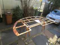
first side wall on a stand, some bits of the second wall arleady on top
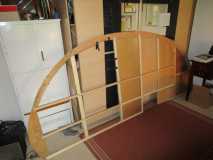
The darn glue wouldn´t cure outside, so I brought everything into the house (the workshop being too small for the wall once assembled)
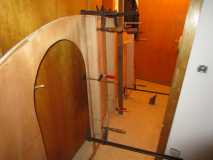
This is how I applied pressure to the glue points since i could not lay down the whole wall and put weights on it
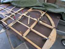
Both walls identicalized...or so. They are the same. But they both need some grating before I can put them up on the trailer bed, once I have the base plate stabilized.
first side wall on a stand, some bits of the second wall arleady on top
The darn glue wouldn´t cure outside, so I brought everything into the house (the workshop being too small for the wall once assembled)
This is how I applied pressure to the glue points since i could not lay down the whole wall and put weights on it
Both walls identicalized...or so. They are the same. But they both need some grating before I can put them up on the trailer bed, once I have the base plate stabilized.
-

Hepcat - Teardrop Advisor
- Posts: 53
- Images: 257
- Joined: Mon Apr 27, 2015 3:17 pm
- Location: Germany