OK, after watching the video, reading the wiring diagram from PD, and a bit of Google searching, what I can tell you is I would NOT follow the advise from the video.
Specifically, at 2:30 in the video he says "this is the ground bar for your 12V." I would NOT use that bus to ground the 12V. The wire from that bus to the negative side of the 12V Converter/Charger is NOT, NO WAY, NO HOW sized to handle the full load of all the 12V circuits added together. He's probably getting away with it because a) the wire is short, and b) he's not running everything at once. (ETA: it's also a good way to make a really noisy radio, if you're using a car audio system.)
Rather look at "Fig 3" in the first post in this thread for the correct way to wire the AC:
http://tnttt.com/viewtopic.php?f=30&t=65938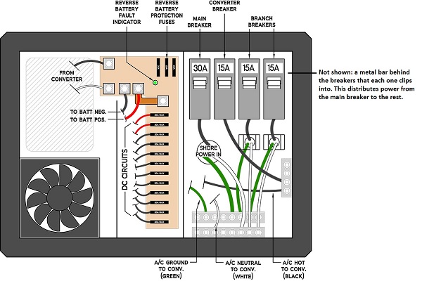
This shows the correct way to wire the AC.
Shore power comes into the PD. The AC-LINE aka HOT or PHASE (black wire) goes to the MAIN BREAKER. The AC-GROUND aka EARTH (green wire with yellow stripe) goes to a connection on the second row up from the bottom of the picture. (The wiring diagram refers to this as the "BOTTOM" row.) The AC-NEUTRAL (white) goes to a connection on the row at the bottom of the picture. (The wiring diagram refers to this as the "TOP" row. I know, confusing, right? Think of it as looking at a top down map of a mountain range and the taller mountain is the "top".)
With the shore power connected (but not actually plugged into shore power!) you can install the AC breakers. You will need to install one breaker for the DC converter and run a black wire from the breaker to the bus bar on the right side of the PD. The three wires (L,N,G) for the DC convertor should come prewired. If not, the LINE goes to the bus on the right and the GROUND and NEUTRAL connect to the respective buses at the bottom, just like the incoming shore power.
For the two additional breaker slots, the AC wiring will go out the back through the slots and attach the same way: LINE to the breaker, GROUND and NEUTRAL to the respective buses. You don't need to connect a wire from the main breaker to the other breaker to feed them -- that is handled by the thick metal bus behind the breakers where they mount to the chassis of the PD. The tie in connection from the battery negative to the AC-NEUTRAL is also handled by the wiring of the PD through the converter section.
For AC outlets always use GFCI outlets everywhere in the trailer. This will protect you in the event that the shore power doesn't have a good solid earth ground.
Now for the DC: The construction of the PD and wiring diagram (the total lack of a DC negative bus bar) give us a hint that the designer intended for the DC returns (aka DC grounds) to be wired in a similar way as a vehicle or RV.

That is fine for RV's that have a metal framework mounted to a big steel chassis, but doesn't work so well for teardrops made of wood. So I suggest adding a separate DC negative bus. Bring all the DC returns back to the negative bus and connect them to the bus. Then with one fat cable (at least the same size as the cable going from the battery positive to the converter that can handle the full DC load) connect the DC return bus to the negative battery terminal. And with one more fat cable connect the battery negative to the connection on the converter.
ETA: a marine converter might actually be better for teardrops, in that boats more often tend to be made from wood or fiberglass and this is usually accounted for in the design.