M116A3 Build

...ask your questions in the appropriate forums BUT document your build here...preferably in a single thread...dates for updates, are appreciated....

Re: M116A3 Build

Postby rjgimp » Sun Jul 02, 2023 9:39 pm

Nice!!!

:thumbsup: :applause: 8) :beer:
-Rob


I hope to make it to a Procrastinators Anonymous meeting someday...
just as soon as the steering committee gets around to scheduling one!
User avatar
rjgimp
500 Club
 
Posts: 849
Images: 7
Joined: Fri Feb 22, 2019 3:59 am
Location: Saint Paul MN

Re: M116A3 Build

Postby lfhoward » Mon Jul 03, 2023 5:10 pm

The 120VAC system functions using either input (shore or inverter). :thumbsup: I measured the full 120 volts at every outlet and the GFCI works properly at all of them.

The second job today was to run the rest of the 12 VDC wiring for the interior lights and fan, which now will connect to power on the other side of the trailer. I also ran three USB cables across the width of the trailer for the inverter and charger and the BMS. Each front compartment now has all the wires that go there, with labels.

The next job for tomorrow will be to install the inverter, charger, and battery, and make all the cables to connect them together and to the DC system.
My off-road camper build on an M116A3 military chassis:
http://www.tnttt.com/viewtopic.php?f=50&t=62581
Tow vehicle: 2008 Jeep Liberty with a 4 inch lift.
User avatar
lfhoward
1000 Club
1000 Club
 
Posts: 1370
Joined: Wed Jan 22, 2014 6:10 pm
Location: Philadelphia, PA

Re: M116A3 Build

Postby pchast » Mon Jul 03, 2023 9:37 pm

You're quickly making good progress. :D
pchast
Platinum Donating Member
 
Posts: 2065
Images: 97
Joined: Mon Jan 28, 2013 5:47 pm
Location: Athens, NY
Top

Re: M116A3 Build

Postby lfhoward » Tue Jul 04, 2023 5:30 pm

The trailer got a bath today.

Image

I continued working on the DC system in the drivers side compartment. Finding room for everything where it can still breathe and stay cool is like a game of Tetris. The inverter (rear) and charger (foreground) blow hot air away from the LiFePO4 battery.

Image

The charger has its own Smart Shunt so I can keep track of its contribution to the system.

Image

The shunt for the battery monitor is mounted underneath the charger and the + and - bus bars are on the back of the charger frame facing the inverter. This keeps them safer than if they were out in the open.

Image

Tomorrow I’ll make the cables to connect all of these components together.
My off-road camper build on an M116A3 military chassis:
http://www.tnttt.com/viewtopic.php?f=50&t=62581
Tow vehicle: 2008 Jeep Liberty with a 4 inch lift.
User avatar
lfhoward
1000 Club
1000 Club
 
Posts: 1370
Joined: Wed Jan 22, 2014 6:10 pm
Location: Philadelphia, PA
Top

Re: M116A3 Build

Postby lfhoward » Tue Jul 04, 2023 8:19 pm

Image

Thinking about how to arrange devices on the back wall of the passengers side compartment.
My off-road camper build on an M116A3 military chassis:
http://www.tnttt.com/viewtopic.php?f=50&t=62581
Tow vehicle: 2008 Jeep Liberty with a 4 inch lift.
User avatar
lfhoward
1000 Club
1000 Club
 
Posts: 1370
Joined: Wed Jan 22, 2014 6:10 pm
Location: Philadelphia, PA
Top

Re: M116A3 Build

Postby bdosborn » Wed Jul 05, 2023 4:05 pm

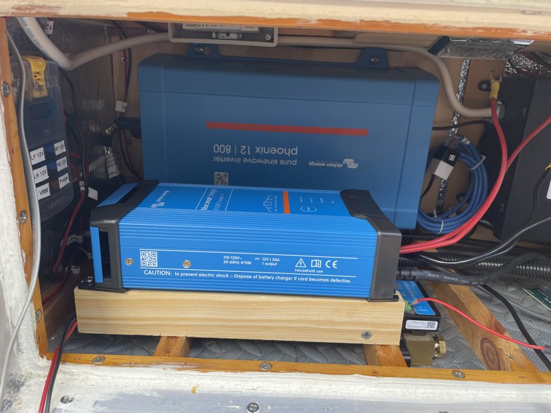
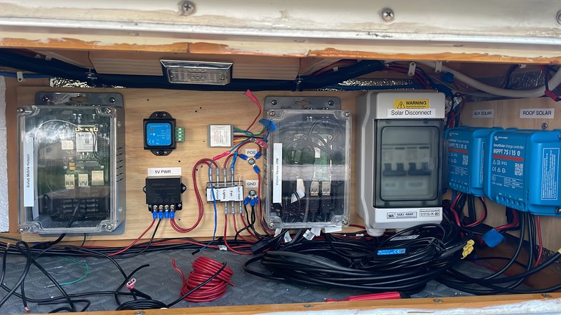
lfhoward wrote:In redoing the 120VAC wiring I reversed the inputs on the Automatic Transfer Switch. Since we most often boondock, I made the inverter the primary AC source. Shore power will be secondary.


I had that arrangement for shore power in the trailer and the relay lasted a year before it went bad. :( I think yours is seldom on shore power so it will probably last for years. Amazon has lots of PV warning stickers, all the cool kids have them. ;)
Bruce
P.S. I'd consider putting a MRBF on your battery positive terminal to supplement the DC breaker. Fuse are much faster acting than breakers and limit the fault current more than breakers do. Breakers are also notorious for failing under high fault current conditions.
2009 6.5'X11' TTT - Boxcar
All it takes is a speck of faith and a few kilowatts of sweat and grace.
Image
Boxcar Build
aVANger Build
User avatar
bdosborn
Donating Member
 
Posts: 5594
Images: 806
Joined: Wed May 05, 2004 11:10 pm
Location: CO, Littleton
Top

Re: M116A3 Build

Postby Tom&Shelly » Wed Jul 05, 2023 8:03 pm

lfhoward wrote:Now I just need a whole bunch of Bruce’s warning & danger stickers! ;)


Here's a good one (found on a hospital bed TV control)

172117

I always love warnings that tell you values should be "appropriate" without telling you what that is.

Tom
174145 170466 173366
Tom&Shelly
Palladium Donating Member
 
Posts: 2464
Images: 2282
Joined: Tue Sep 05, 2017 3:27 pm
Location: New Mexico
Top

Re: M116A3 Build

Postby lfhoward » Wed Jul 05, 2023 8:32 pm

bdosborn wrote:P.S. I'd consider putting a MRBF on your battery positive terminal to supplement the DC breaker. Fuse are much faster acting than breakers and limit the fault current more than breakers do. Breakers are also notorious for failing under high fault current conditions.


Got it. :thumbsup:

Image

Today’s progress was in the passengers side compartment.

Image

The components are arranged differently than I was envisioning in the photo I posted last night. I think this will work better for cooling as well as just being a simpler layout.

From left to right: Raspberry Pi cellular wifi hotspot, 5 volt power supply, auxiliary fuse box, 2 relays above, Raspberry Pi running Venus OS, solar power disconnect / breakers, and 2 solar charge controllers.
My off-road camper build on an M116A3 military chassis:
http://www.tnttt.com/viewtopic.php?f=50&t=62581
Tow vehicle: 2008 Jeep Liberty with a 4 inch lift.
User avatar
lfhoward
1000 Club
1000 Club
 
Posts: 1370
Joined: Wed Jan 22, 2014 6:10 pm
Location: Philadelphia, PA
Top

Re: M116A3 Build

Postby bdosborn » Thu Jul 06, 2023 7:04 am

Looking awesome. :thumbsup: 
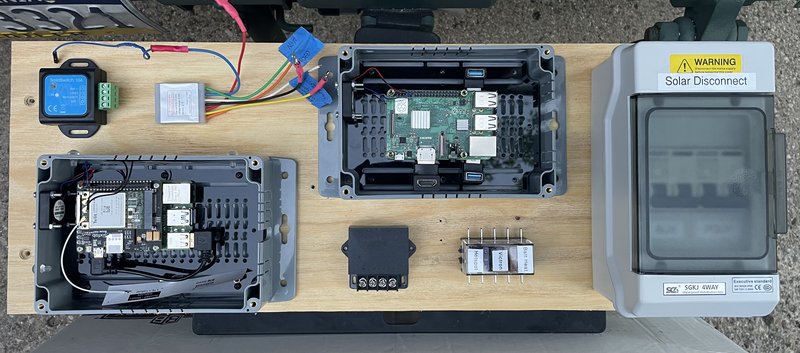
I use the PV circuit breakers in the van a lot more often than I thought I would. It makes it super easy to tinker with things.
Bruce
2009 6.5'X11' TTT - Boxcar
All it takes is a speck of faith and a few kilowatts of sweat and grace.
Image
Boxcar Build
aVANger Build
User avatar
bdosborn
Donating Member
 
Posts: 5594
Images: 806
Joined: Wed May 05, 2004 11:10 pm
Location: CO, Littleton
Top

Re: M116A3 Build

Postby lfhoward » Thu Jul 06, 2023 9:38 am

Making battery cables today. I should have the system up and running by this afternoon if the rain holds off!
My off-road camper build on an M116A3 military chassis:
http://www.tnttt.com/viewtopic.php?f=50&t=62581
Tow vehicle: 2008 Jeep Liberty with a 4 inch lift.
User avatar
lfhoward
1000 Club
1000 Club
 
Posts: 1370
Joined: Wed Jan 22, 2014 6:10 pm
Location: Philadelphia, PA
Top

Re: M116A3 Build

Postby featherliteCT1 » Thu Jul 06, 2023 5:06 pm

I am now picturing you painting your trailer Victron blue, wearing a Victron T shirt and a Victron hat. :thumbsup:
featherliteCT1
1000 Club
1000 Club
 
Posts: 1167
Joined: Wed Dec 28, 2016 6:54 am
Location: Southern Indiana
Top

Re: M116A3 Build

Postby lfhoward » Thu Jul 06, 2023 5:43 pm

featherliteCT1 wrote:I am now picturing you painting your trailer Victron blue, wearing a Victron T shirt and a Victron hat. :thumbsup:

:lol:

Finishing up the DC wiring in the drivers side compartment.
Image

The battery is in!
Image

I’m going to put the bus bars on it and get the BMS connected while there is still light outside.
My off-road camper build on an M116A3 military chassis:
http://www.tnttt.com/viewtopic.php?f=50&t=62581
Tow vehicle: 2008 Jeep Liberty with a 4 inch lift.
User avatar
lfhoward
1000 Club
1000 Club
 
Posts: 1370
Joined: Wed Jan 22, 2014 6:10 pm
Location: Philadelphia, PA
Top

Re: M116A3 Build

Postby lfhoward » Sat Jul 08, 2023 6:22 pm

Everything is up and running. :D

Image

The inverter shows up in the upper right quadrant as expected, but the smart shunt on the shore charger does not show up on the upper left in AC input. I selected AC Charger for the shunt’s job, but this does not seem to show up anywhere on the GX/VRM except under individual devices in the menu. It does work, however, if I fudge it and make it a PV Charger. You’ll notice “Shore” is there with “Roof” and “Aux” on the lower right. This is a bug Victron needs to sort out.

I do have to wire up two Victron SolidSwitch relays (for the battery heater and ceiling fan) so I can tie them into the GuiMods relays that turn on/off based on RuuviTag temperature data. This is a job for another day, but it will be fun.
My off-road camper build on an M116A3 military chassis:
http://www.tnttt.com/viewtopic.php?f=50&t=62581
Tow vehicle: 2008 Jeep Liberty with a 4 inch lift.
User avatar
lfhoward
1000 Club
1000 Club
 
Posts: 1370
Joined: Wed Jan 22, 2014 6:10 pm
Location: Philadelphia, PA
Top

Re: M116A3 Build

Postby bdosborn » Sat Jul 08, 2023 8:29 pm

Well done! :thumbsup:
Bruce
2009 6.5'X11' TTT - Boxcar
All it takes is a speck of faith and a few kilowatts of sweat and grace.
Image
Boxcar Build
aVANger Build
User avatar
bdosborn
Donating Member
 
Posts: 5594
Images: 806
Joined: Wed May 05, 2004 11:10 pm
Location: CO, Littleton
Top

Re: M116A3 Build

Postby bdosborn » Fri Jul 14, 2023 12:10 pm

Something I thought you might like to know about:

The van garage got pretty hot yesterday, about 95F or so and the Bluetooth for the Cerbo shutdown. I found out about it when I got a temperature alarm and found that none of the Mopeka or Ruuvi devices were reporting. It looks like its a known thing with the Cerbo and they recommend a Bluetooth dongle if you're using Ruuvi devices. I think the Cerbo is just a repackaged Raspberry Pi so I wonder if you'll run into the same issue...
Cerbo GX Bluetooth Issue

Bruce
P.S. the Bluetooth came back on after it got cooler that night.
2009 6.5'X11' TTT - Boxcar
All it takes is a speck of faith and a few kilowatts of sweat and grace.
Image
Boxcar Build
aVANger Build
User avatar
bdosborn
Donating Member
 
Posts: 5594
Images: 806
Joined: Wed May 05, 2004 11:10 pm
Location: CO, Littleton
Top

PreviousNext

Return to Build Journals

Who is online

Users browsing this forum: No registered users and 16 guests