What I have is 4 x 210 watt Kyocera panels -
then a Outback - Flexmax 80 charge controller
& a set of 400 amp hour batteries.
the question is what size DC breakers & where ?

should the panels be wired + & - ?
and what size wiring goes where ?
I have the ac side under control....
its the DC side that I needs some help with..
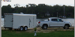
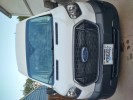
http://overthetopcargotrailer.blogspot.com/
Here are some tips for you guys
Maximum Open Circuit Voltage (VOC)
• VOCistheunloadedvoltagegeneratedbythesolararray. • Greater than 145VDC Charge Controller suspends operation to protect components • 150DC max open circuit voltage with the coldest environment
NOTE: Although the Charge Controller shuts down at a voltage greater than 145VDC, it can withstand up to 150VDC from the array; anything higher than 150VDC will damage the Charge Controller).
Check the PV array voltage before connecting it to the Charge Controller (see page 76)
Wire and Disconnect Sizing
FLEXmax 80
• TheoutputcurrentlimitoftheFLEXmax80is80amps • Use a minimum of 4 AWG (21.15 mm2) wire for the output between the FLEXmax 80 and the battery
bus bar conductors • InstallOutBackOBB-80-150VDC-PNLbreakersfordisconnectandovercurrentprotection • The largest PV array that can connect to a Charge Controller must have a rated short-circuit current
of 64 amps or less under STC (Standard Test Conditions).
NOTE: Input conductors and circuit breakers must be rated at 1.56 times the short-circuit current of the PV array. OutBack 100% duty continuous breakers only need to be rated at 1.25 times the short- circuit current.
NOTES: • Each Charge Controller requires its own PV array. DO NOT PARALLEL Charge Controller PV+ and PV-
TERMINALS ON THE SAME ARRAY!
• An optional battery Remote Temperature Sensor (RTS) is recommended for accurate battery recharging (only one RTS is needed for multiple OutBack Series Inverter/Chargers and Charge Controller units when an OutBack HUB and a MATE are parts of the system). When one RTS is used, it must be connected to the component plugged into the Port 1 of the HUB.
FLEXmax 80
The Charge Controller is a buck type converter with the following properties: • 80 amp DC output current limit (default setting) • Listed to operate continuously at 80 amps (40°C/104° F)
With an 80 amp Charge Controller output current limit and PV array output higher than 80 amps offers little, if any, current boosting or Maximum Power Point Tracking advantage; in effect, any excess power beyond 80 amps is lost.
For NEC* compliance and the Charge Controller’s 80 amp output rating / MPPT capabilities, the largest PV array input must not exceed a rated short-circuit current of 64 amps.
Battery Side of the Controller
• All OutBack Power circuit breakers (OBB-XX) are 100% continuous-rated type breakers • The conductors connected to the breakers must have a 125% safety factor applied (i.e., an 80 amp
breaker must have a 100-amp conductor connected when used at its full 80-amp rating)
PV Side of the Controller
• UL* requires a 125% safety multiplier (before NEC calculations) • NEC* requires a 125% safety multiplier (after UL calculations). • The 156% safety multiplier is specific in the NEC* to PV applications only – this “dualâ€


 I posted some new pictures just now on my blog. They covering wiring, fuses and fuse holders for dc wiring. Really great charts for someone doing d/c wiring of any kind. I wish I would have found them sooner.


