The Poet Creek Express - Foamie Hybrid

Canvas covered foamies (Thrifty Alternatives...)

Moderator: eaglesdare

Re: The Poet Creek Express - Foamie Hybrid

Postby GPW » Sun Jan 06, 2013 2:51 pm

Just keep FOCUSED on how NICE it’s going to be when it’s Done !!! 8) 8) 8) :thumbsup: :applause: .. how about showing some nice salads or perhaps a squash ... :R
There’s no place like Foam !
User avatar
GPW
Gold Donating Member
 
Posts: 14920
Images: 546
Joined: Thu Feb 09, 2006 7:58 pm
Location: New Orleans

Re: The Poet Creek Express - Foamie Hybrid

Postby KCStudly » Fri Jan 11, 2013 12:00 am

Veggies are good, and the "Sprint to Spring" contest is starting up again, although this year's prize has been reduced to $250 per winner.

Installing the wall blocking continues, and toward the bottom of this post are some screen shots of the preliminary hatch actuator arrangement; already subject to change.

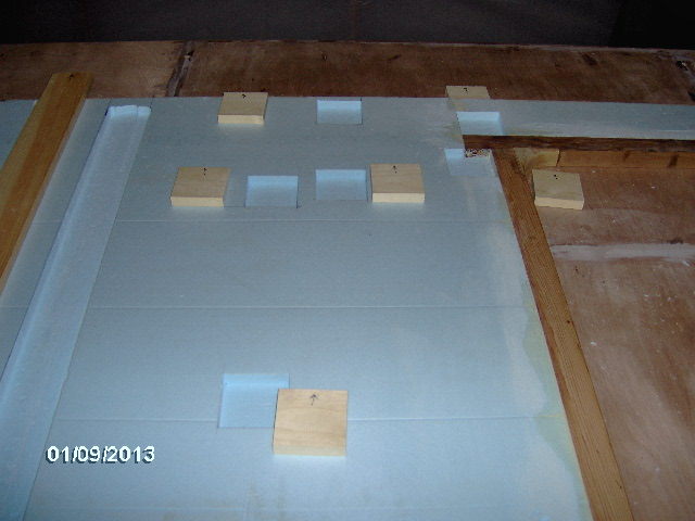
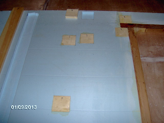
Yesterday (Wednesday) I started by going around and making sure that all of the street side interior blocks fit their intended recesses properly. A kiss here and there with the sanding block, cheap serrated boning knife, and/or extended razor knife while indicating up orientation with a sharpie for repeatability brought me to here.
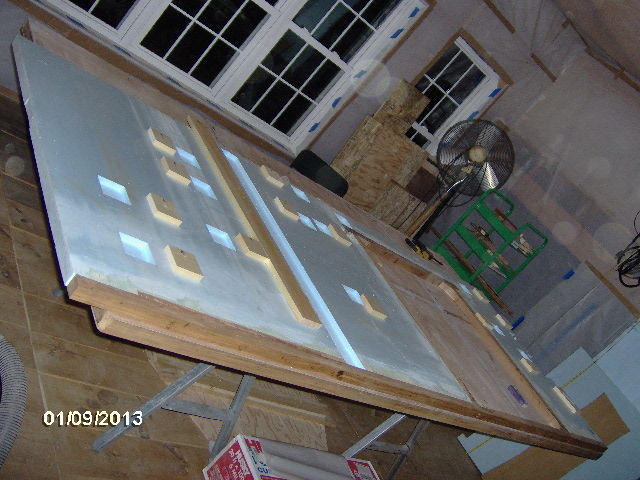
Image

The front all ready to go with a bit of plastic coated freezer paper under the exposed edge to protect the cabin floor/work table.
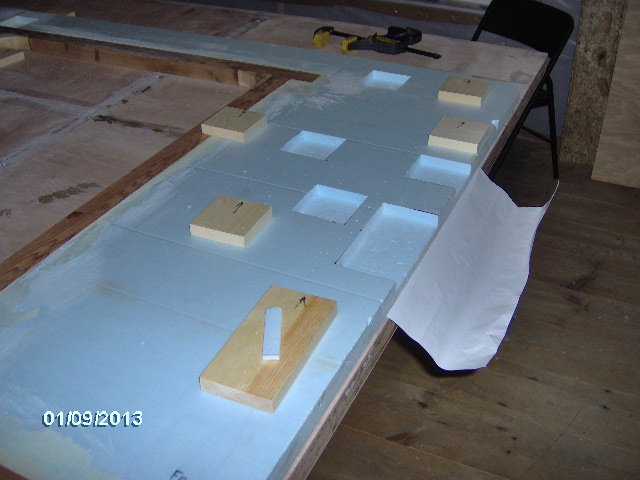
Image

Mid cabin.
Image

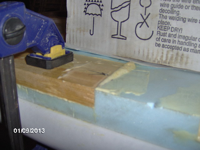
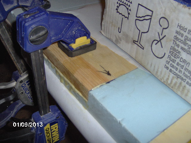
Started gluing at the front. The ones at the edge I just clamped. Shop temp started at 46F and went to 48F with the turd burning (40F outside, no woodstove downstairs). Seemed to take forever for the GG to kick and after sitting in my car all day it flowed like molasses. Used too much on the first piece shown here. Also note the cardboard box; welding wire spool used to weigh down additional blocks in the field.
Image
Image
Note the freezer paper (plastic side down) between the wire box and glue.

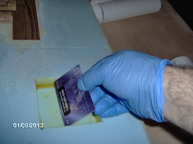
Found this trick here on the forum somewhere (wish I knew who to credit). Use those cheap temporary credit/membership card promotions that always seem to come in the mail as glue spreaders. Worked perfectly for my 3-1/2 inch wide recesses.
Image

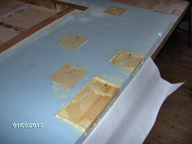
Plenty of clean-up required at the front.
Image

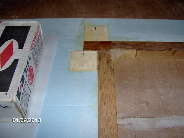
Same again at mid cabin; dome light and coat hook locations.
Image

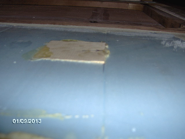
One of the shelf locations at the front I tried to get away with just one wire spool on two blocks, but I must not have got it centered well because one of the blocks lifted at the top.
Image
Will have to work on my sanding technique; glad I tested.

I only had so many boxes of wire and so much gumption (and was a little leery of doing the bulkhead location without a long strong back to clamp down, so I finished up at the mid cabin.
Image

Turned to fiddling with the plans and linear actuators to make sure I know what I may or may not need for blocking before going too far. Messed around with the paper plans and a compass a bit before deciding that I could do it much more efficiently using CAD.

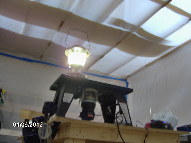
Some deferent perspective shots of the turd before shutting down for the night.
Looking up
Image

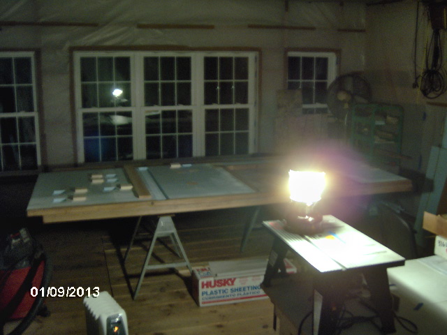
Ambiance (shop lights out).
Image

And the last gasp upon shut down, blue and gold.
Image

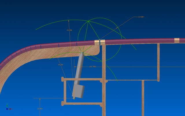
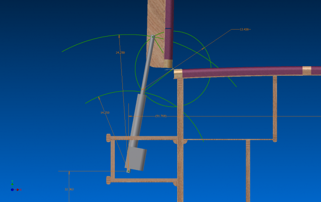
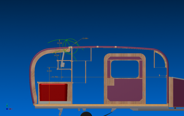
This evening I got serious about attempting to incorporate the freebie linear actuators to raise and lower the galley hatch. Here is a screen shot looking through the curb side wall (with the street side wall “turned off” for better contrast).
Image

And a closer shot of the hinge area.
Image

The two green arcs centered on the cabin side anchor point of the actuator represent the extended and retracted lengths of the actuator. The circle represents the path of the rod end anchor point on the hatch rib about the hinge. The equilateral triangle has its base in a line with the fixed (cabin side) of the actuator so that the action is spread equally about the point where the rod is at 90 degrees to the hinge centerline. This is the point where the actuator travel is most efficient providing the most power to lift the hatch and least binding (lowest vector force trying to rip the hinge from its spar).

Through iteration, by varying the distance that the rod end was from the hinge (diameter of the circle), and the height of the fix pivot point on the cabin side above the floor (and thus the dependent location of the pivot horizontally) I was able to find the end points that corresponded to my 95 deg hatch travel (from closed to open). I did allow for a little positive closure so that the actuator pulls the hatch into the seals for sure.

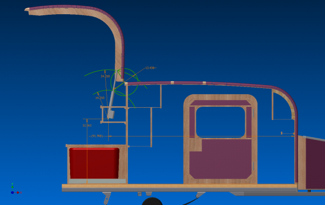
Here is the same set up with the hatch open, and a closer view.
Image
Image

This first attempt was assuming that the actuators would be against the side walls and would be bolted with offset brackets through the outermost hatch ribs. When I started looking at the offsets from the side walls inboard, I was not happy with the cantilever distances, nor the amount of shelving that I would lose to the chases required to box in the actuators. Also, I thought I could do better by making the circle larger, thereby changing the effective fulcrum point and reducing the leverage, stress and load on the actuators. So I moved the actuators inboard to the two more centrally located hatch ribs, detailed a bracket tab that will straddle the ribs in pairs, and moved the cabin side pivot point down and closer to the bulkhead wall. Sorry, ran out of time to get any more screen shots this evening, but will refine it further and post something up as it develops. The new arrangement will steal space from both upper galley shelves, but by centering on these ribs with the actuators directly behind the shelf mullions, and down closer to the shelf ledgers, which are in turn located at the bulkhead xmbr reinforcements, it will add strength while stealing less of the useful shelf space.

Progress is progress. Just need to keep putting time in.

Night.
KC
My Build: The Poet Creek Express Hybrid Foamie

Poet Creek Or Bust
Engineering the TLAR way - "That Looks About Right"
TnTTT ORIGINAL 200A LANTERN CLUB = "The 200A Gang"
Green Lantern Corpsmen
User avatar
KCStudly
Donating Member
 
Posts: 9640
Images: 8169
Joined: Mon Feb 06, 2012 10:18 pm
Location: Southeastern CT, USA

Re: The Poet Creek Express - Foamie Hybrid

Postby GPW » Fri Jan 11, 2013 7:31 am

KC, not to be contrary , but wouldn’t leaning the struts in the other direction put less stress loads on the struts and hatch ? What about “wind loads” ... you have a big “sail" sticking up there and short “leverage” .... :thinking:
Project’s coming along Nicely !!! Anxious to see the sub assemblies come together ... 8)
There’s no place like Foam !
User avatar
GPW
Gold Donating Member
 
Posts: 14920
Images: 546
Joined: Thu Feb 09, 2006 7:58 pm
Location: New Orleans
Top

Re: The Poet Creek Express - Foamie Hybrid

Postby Wobbly Wheels » Fri Jan 11, 2013 11:01 am

KC, not to be contrary , but wouldn’t leaning the struts in the other direction put less stress loads on the struts and hatch ?


I was wondering about that too. It looks like the first 1/4 or so of the stroke would be putting a lot of force onto the hinge pin.
There must be something I'm not seeing.

Also, does the upper eye mount to the outer rib or to a bridge between the outer two ?
User avatar
Wobbly Wheels
Donating Member
 
Posts: 1080
Joined: Tue Mar 15, 2011 9:51 am
Top

Re: The Poet Creek Express - Foamie Hybrid

Postby ghcoe » Fri Jan 11, 2013 1:27 pm

Another thought is does the hinge have to be so far forward? I would think that if the hinge was farther back it would cut down on the sail effect as well as door wieght. Just a thought.
George.

Gorrilla Glue, Great Stuff and Gripper. The three G's of foamie construction.

My build viewtopic.php?t=54099
Working with flashing for foamie construction viewtopic.php?f=55&t=60303
Making a hot wire http://tnttt.com/viewtopic.php?f=55&t=55323
User avatar
ghcoe
1000 Club
1000 Club
 
Posts: 1982
Joined: Fri Dec 11, 2009 11:20 pm
Location: SW Idaho
Top

Re: The Poet Creek Express - Foamie Hybrid

Postby KCStudly » Fri Jan 11, 2013 5:45 pm

This was a very preliminary “shot” at a first iteration, and the fabulous thing about sharing the design process here is that you all have been able to help me find a few flaws in my layout. Thanks a bunch. I mean it.

ghcoe wrote:Another thought is does the hinge have to be so far forward? I would think that if the hinge was farther back it would cut down on the sail effect as well as door wieght. Just a thought.


When I was working on the profile and location of the hinge many moons ago, my thinking was that: (1) I wanted the hinge to be near the bulkhead for the strength and rigidity that it would provide; (2) I wanted the hatch when opened to not hit me in the head; (3) I was hoping that it would at least cover the galley and, if lucky, part of me when standing underneath in a light non-driving rain. None of these design parameters have changed.

I think after reading GPW’s last post I had a “forest for the trees” moment (a moment that lasted for months until now) where I may have measured the hatch “up” position from the floor and not from the ground. ( :duh: ) So, yeah, it was sticking way up there and causing me to think that I needed more angular travel than I really do. (“DING-DING-DING You Win The Prize Bells” going off for GPW… GeeP dub to his friends :D ).

So I am currently (as I type this) going into the model and adjusting the “throw” of the hatch down from 95 to 65 degrees from closed to open, which should give about 7 feet from level ground at the hatch sill when opened. When open the hatch will be a lot more like a hump back or airfoil, than a scoop, and will shade/cover more ground behind the galley. That reduction in travel will also have a huge effect on my ability to move the hatch end anchor point of the actuator away from the hinge. :phew:

GPW wrote:... wouldn’t leaning the struts in the other direction put less stress loads on the struts and hatch ?


Yes, if the center of mass of the hatch relative to the hinge is perpendicular to the actuator axis when at mid stroke that is the ideal situation (light bulbs going off…where is the center of mass of the hatch? Let’s check the model and see!). That way the actuator has the largest possible lever arm through the largest range of the travel (dwell point). As stated I have already looked at moving the cabin end anchor point down and forward. Being able to move the hatch end anchor point farther back from the hinge (due to the amount of rotation required being less for the same overall actuator stroke length) will only improve this.

As noted, the previous sketch is by no means a final design, just a place to start as I am sharing the whole process (warts and all) in near real time. 8) In fact I just looked at where the model says the center of gravity is for the hatch and not surprisingly, it is “in the middle”.

GPW wrote: What about “wind loads” ... you have a big “sail" sticking up there and short “leverage” .... :thinking:


That will get much better after this evening’s revisions. The actuators are good for 500 lbs static load each. We can look at the leverage and wind loading, but my guess right now is that I need to be more concerned with attaching them to something solid on the camper rather than them failing outright or the hinge pulling out.

BTW, In case I wasn’t clear, these are screw type linear actuators; no springs and no hydraulics. When they are switched off they lock into whatever position they are in at the moment.

GPW wrote: Project’s coming along Nicely !!! Anxious to see the sub assemblies come together ... 8)


Thanks a lot for your input! A am anxious, too. :thumbsup:

Wobbly Wheels wrote: There must be something I'm not seeing.


Naw, it was the damn forest getting in the way of the lovely trees. :?

Wobbly Wheels wrote: Also, does the upper eye mount to the outer rib or to a bridge between the outer two?


In those sketches it wasn’t mounted to anything. The actuator was just sort of overlaid into the model floating in space so that I can get the kinks worked out of the geometry. In the 2nd (not shown) and soon to be 3rd iteration the actuators will be located under each of the two middle hatch ribs with two tabs; one on each side of each rib, sandwiching the rib and rod end bolt in double shear. That way the boxed chases for the actuators (later) can align behind the mullions in the upper cabinet shelves for a more streamlined use of the space; and the weight of the hatch will be spread more equally (less span between actuators) requiring less (…still no) spar members in the field of the hatch (TLAR method). Although I will include a little bit of positive closing action pulling the hatch into the seals, I still plan to use draw down latches, so will not be relying on the actuators for that.

Looky here, I have already saved at least a dozen errant screw holes from needing to be patched in the finished product! Power of CAD and the best damn trailer design support team in the world (that’s you guys).

Now back to work. Stay tuned.
KC
My Build: The Poet Creek Express Hybrid Foamie

Poet Creek Or Bust
Engineering the TLAR way - "That Looks About Right"
TnTTT ORIGINAL 200A LANTERN CLUB = "The 200A Gang"
Green Lantern Corpsmen
User avatar
KCStudly
Donating Member
 
Posts: 9640
Images: 8169
Joined: Mon Feb 06, 2012 10:18 pm
Location: Southeastern CT, USA
Top

Re: The Poet Creek Express - Foamie Hybrid

Postby RandyG » Fri Jan 11, 2013 8:31 pm

If those actuators are loaded for 500 then you dont need 2 of them do ya? You could use the other for something else or send it my way :D.
Do you think if you attached them to the bulkhead it would be a stronger point then mounting to the side wall? Would they give you enough travel from that point? I think I can see the machinist making some custom mounting brackets in the future.
Randy
Aircraft fabricator, novice carpenter, electrical apprentice, audio engineer dropout.
Build thread - http://www.tnttt.com/viewtopic.php?f=50&t=54126
User avatar
RandyG
500 Club
 
Posts: 695
Images: 115
Joined: Thu May 10, 2012 6:52 pm
Top

Re: The Poet Creek Express - Foamie Hybrid

Postby wagondude » Fri Jan 11, 2013 10:11 pm

Maybe you could hide the actuators and use a bell crank and pushrod to open the hatch. Maybe not. That would just be complication for the sake of complication. 8)
Bill

TnTTT ORIGIONAL 200A LANTERN CLUB
101137
User avatar
wagondude
1000 Club
1000 Club
 
Posts: 1535
Images: 35
Joined: Sun Jan 16, 2011 7:41 pm
Location: Land of the Jayhawks
Top

Re: The Poet Creek Express - Foamie Hybrid

Postby KCStudly » Fri Jan 11, 2013 11:15 pm

RandyG wrote:If those actuators are loaded for 500 then you dont need 2 of them do ya?

The static rating is 500 lbs. which means if they are sitting there (I assume fully extended) and you load them (I assume) in compression they won't fail (spin down, strip the internal threads, blow out, or otherwise collapse) up to 500 lbs. each. The dynamic load rating is only 100 lbs. each, which means that they are only able to move against 100 lbs. each. I will eventually do a wind load and finite element analysis (FEA) to try to predict what the leveraged forces are on the final arrangement. Say the hatch weighs 60 to 80 lbs. (a guess) and the CG is 3x the distance from the hinge that the rod ends are, then the actuators could be attempting to lift most of up to 240 lbs. combined. There are other factors, including what angle the hatch is at in any given moment (i.e. where the CG is relative to the hinge) and vectors (i.e. loses in the application of force because the rods are not always 90 deg to the hinge throughout their travel). Hence, I will probably need at least two actuators. I won't do it if it takes more than 2.

These numbers are WAG's (wild ass guesses) for the sake of discussion. It is entirely possible that two will be inadequate. If I had my choice I would have selected the 12 inch throw units to cut the leverage down even more.

RandyG wrote:You could use the other for something else or send it my way :D.

If I have any left over you are first on my list, Randy.

RandyG wrote:Do you think if you attached them to the bulkhead it would be a stronger point then mounting to the side wall? Would they give you enough travel from that point?

I think that the side wall would be stronger due to the direction that the force would be applied, but that the cantilevered brackets required to step them off of the wall would add a fair amount of twist; prying action that would try to rip the brackets away from the walls. I briefly considered moving the outer most ribs in away from the walls so that the actuator could be closer to the inside of the wall, and the rod would still be close to the rib (on the outside of the rib), but I did not like the idea of moving the rib that far away from the edge of the hatch (the edge of the hatch needs to be ridged to make a good seal and the rib does that so long as it is close to the edge). Part of the problem is that the body of the actuators are (...er, from memory) something like 1.55 inches wide, and the mounting lug and rod are 0.7 and 0.8 wide, respectively. By the time you add adequate thickness for the brackets and thickness of the rib, it gets kind of hinky.

Now that I have rearranged the geometry to under the ribs instead of to the side, I should probably go back and reconsider locating them outboard. even if I still mount them to the bulkhead, it would be very close to the side wall and more rigid than further out on the bulkhead. However, with the diaphragm effect from the shelves and inside cabinets boxing in the bulkhead, the xmbr in the bulkhead that supports the galley shelf ledger, and the ledger itself, I feel pretty strongly that the inboard location would be fine.

RandyG wrote:I think I can see the machinist making some custom mounting brackets in the future.

Touching finger to tip of schnozola repeatedly, Randy nose. :thumbsup: In fact I spent some time this evening modeling some aluminum beauties.

The 3rd generation arrangement is about 90/ct complete, but just a little too early for screen shots (ran out of time).

wagondude wrote:Maybe you could hide the actuators and use a bell crank and pushrod to open the hatch. Maybe not. That would just be complication for the sake of complication. 8)

I have kept that in mind throughout, but it doesn't seem to be necessary, and I think I would rather give up a little of the upper shelf space in the galley, rather than cabinet space in the cabin. I do plan on having little access covers in the back of the cabin cabinets where I can reach through and pull out quick pins in the lower anchor pivot points, just in case there is an electrical failure and I need to get into the hatch manually. The other neat thing I am thinking of doing is using a weather proof switch located under a little hatch on the lower outside corner of the wall where it can be secured closed and locked by folding the switch cover under the hatch draw down latch (killing two birds with one lock).

It doesn't hurt to plan, plan, and plan some more (unless you want to actually finish someday :? ). Like I have said, the devil is in the details.

Thanks for participating!
KC
My Build: The Poet Creek Express Hybrid Foamie

Poet Creek Or Bust
Engineering the TLAR way - "That Looks About Right"
TnTTT ORIGINAL 200A LANTERN CLUB = "The 200A Gang"
Green Lantern Corpsmen
User avatar
KCStudly
Donating Member
 
Posts: 9640
Images: 8169
Joined: Mon Feb 06, 2012 10:18 pm
Location: Southeastern CT, USA
Top

Re: The Poet Creek Express - Foamie Hybrid

Postby ghcoe » Fri Jan 11, 2013 11:41 pm

Ok, so here is a thought. Instead of having your two shelves below the hatch, put a face on those shelves that will go up to the roof line. This would act as a bulk head of sorts. Then your lifts would be in your dead space between the rear of the trailer and the shelves. This would cut about half of your lift height and cover the cooking area better. It would also curtail wanting to put something too tall on the top shelf and having your hatch close down on it and causing damage to something.
Attachments
hatch.png
hatch.png (152.05 KiB) Viewed 2499 times
George.

Gorrilla Glue, Great Stuff and Gripper. The three G's of foamie construction.

My build viewtopic.php?t=54099
Working with flashing for foamie construction viewtopic.php?f=55&t=60303
Making a hot wire http://tnttt.com/viewtopic.php?f=55&t=55323
User avatar
ghcoe
1000 Club
1000 Club
 
Posts: 1982
Joined: Fri Dec 11, 2009 11:20 pm
Location: SW Idaho
Top

Re: The Poet Creek Express - Foamie Hybrid

Postby KCStudly » Sat Jan 12, 2013 10:11 am

Thanks ghcoe. At first I thought your idea would make for a lot of rework, but then I thought about it some and figured it wouldn't be that bad. I would need to shorten the hatch ribs (not much work), and I would need to add to the shelf frame (doable); some more wall blocking would probably be a good idea. So without checking the model I started to consider it.

But then you have to consider where the actuator needs to be relative to the hinge. The only way to (sort of) hide the actuator in the cabinet is for the cabinet to be behind the hinge line so that the rod can reach up without slicing through or running into the hinge. Otherwise we would be looking at some sort of under slung bell crank and laying the actuators down closer to horizontal.

And my roof and hatch skin blanks have already been cut, so I would have to cut a narrow slice off of the hatch skin and scab it onto the roof. I have issues with that.

After working on the arrangement some more and resolving the issue with how far I was showing the hatch lifted (it opens a lot less now in the model than I have shown so far) I believe that the solution can be much easier.

I do like your advice about capping the top shelf to prevent interference issues, and, as stated previously, I'm still not settled on how I will secure/contain stowed items. In the back of my mind I have been thinking all along that I want to keep the upper shelves as simple as possible so that if I decide to pull them out later to change the arrangement, then it wouldn't be such a big issue. So for now the plan is to just leave them open and probably use plastic totes to contain everything.

Thanks for contributing. There are no bad ideas when designing. At this stage ideas are just options, and options are good. :thumbsup:
KC
My Build: The Poet Creek Express Hybrid Foamie

Poet Creek Or Bust
Engineering the TLAR way - "That Looks About Right"
TnTTT ORIGINAL 200A LANTERN CLUB = "The 200A Gang"
Green Lantern Corpsmen
User avatar
KCStudly
Donating Member
 
Posts: 9640
Images: 8169
Joined: Mon Feb 06, 2012 10:18 pm
Location: Southeastern CT, USA
Top

Re: The Poet Creek Express - Foamie Hybrid

Postby ghcoe » Sat Jan 12, 2013 11:42 am

No problem.

I am dealing with some design problems myself. I really like the hatch style door in the back, but with my design I am planning on installing a roof rack to haul kayaks/bikes. With the hatch design to lift for head clearance when up I will have interference with the kayaks. So the question is, do I want to remove the kayaks to gain access to the galley every time, or change my plan to a more undesirable (in my opinion) barn door style galley access? I like the hatch idea better because it does act as a galley cover when up, barn doors are.... well, just doors! :roll:
I like everything to have a purpose if possible.
George.

Gorrilla Glue, Great Stuff and Gripper. The three G's of foamie construction.

My build viewtopic.php?t=54099
Working with flashing for foamie construction viewtopic.php?f=55&t=60303
Making a hot wire http://tnttt.com/viewtopic.php?f=55&t=55323
User avatar
ghcoe
1000 Club
1000 Club
 
Posts: 1982
Joined: Fri Dec 11, 2009 11:20 pm
Location: SW Idaho
Top

Re: The Poet Creek Express - Foamie Hybrid

Postby KCStudly » Sat Jan 12, 2013 3:14 pm

If I were you I would definitely go with the barn doors with perhaps an over hanging shroud to give it a little shape and provide a drip edge to stand under.

I just made the same recommendation based off of one of GPW's sketches in another thread. Let me take a look for it.

Couldn't find it. I hope GPW doesn't mind me raiding his photo gallery. This is his sketch.
Image

IIRCC this concept is intended to improve aerodynamic fuel efficiency. Not sure it is supported by science, I just do not recall, but maybe.

Disregard the bed and interior layout. Make it your own, maybe. I'm sure GPW would be happy to have you "steal" his concept.
KC
My Build: The Poet Creek Express Hybrid Foamie

Poet Creek Or Bust
Engineering the TLAR way - "That Looks About Right"
TnTTT ORIGINAL 200A LANTERN CLUB = "The 200A Gang"
Green Lantern Corpsmen
User avatar
KCStudly
Donating Member
 
Posts: 9640
Images: 8169
Joined: Mon Feb 06, 2012 10:18 pm
Location: Southeastern CT, USA
Top

Re: The Poet Creek Express - Foamie Hybrid

Postby GPW » Sat Jan 12, 2013 4:39 pm

With Pleasure !!! It’s all there for YOU!!! ;) :beer:
There’s no place like Foam !
User avatar
GPW
Gold Donating Member
 
Posts: 14920
Images: 546
Joined: Thu Feb 09, 2006 7:58 pm
Location: New Orleans
Top

Re: The Poet Creek Express - Foamie Hybrid

Postby Wobbly Wheels » Sat Jan 12, 2013 5:50 pm

George: at the risk of going too far OT, what about an arrangement like this ?
Image
The hatch could flip up to horizontal with light springs and provide an awning without projecting too far back.
Split barn doors below it wouldn't protrude past the protection of the awning either and would also give you some side protection from wind & rain.
User avatar
Wobbly Wheels
Donating Member
 
Posts: 1080
Joined: Tue Mar 15, 2011 9:51 am
Top

PreviousNext

Return to Foamies

Who is online

Users browsing this forum: No registered users and 7 guests

cron